当前位置:网站首页>Serial port receives a packet of data
Serial port receives a packet of data
2022-07-08 00:56:00 【Zelonal】
With single chip microcomputer N32G435 For example , Serial communication is GPS, Cooperation timer 2 Receive a packet of data .
By continuously updating the timer in the serial port receiving interrupt 2 The count of , Until the timer 2 Interrupt overflow ( General timing 10ms), Indicates that a packet of data has been received .
In the course of debugging , It is found that the receive interrupt has only entered once , A string received only one character , After online inquiry, several solutions have been obtained , as follows :
- The interrupt program takes too long , As a result, subsequent data cannot be received when it arrives .
- Interrupt clear flag bit .
- Serial port interrupt priority is too low , Cause interrupt nesting . Set the priority to the highest .
Interrupt clearing has been added to my interrupt function , It also improves interrupt priority , But it didn't solve , Later, it was found that... In the receiving function would be interrupted printf(); Function delete , Found to return to normal , Should be printf(); The function takes too long to receive the following data !!
Next, I will make a note of the configuration process and processing :
//  Timer 2 Initialize configuration
void TIM2_Int_Init(u16 arr,u16 psc)
{
	TIM_TimeBaseInitType TIM_TimeBaseInitStructure;
	NVIC_InitType        NVIC_InitStructure;

	RCC_EnableAPB1PeriphClk(RCC_APB1_PERIPH_TIM2,ENABLE);  /// Can make TIM2 The clock

  	TIM_TimeBaseInitStructure.Period = arr; 	// Automatic reload load value
	TIM_TimeBaseInitStructure.Prescaler=psc;  // Timer frequency division
	TIM_TimeBaseInitStructure.CntMode=TIM_CNT_MODE_UP; // Upcount mode
	TIM_TimeBaseInitStructure.ClkDiv=TIM_CLK_DIV1;

	TIM_InitTimeBase(TIM2,&TIM_TimeBaseInitStructure);// initialization TIM2
	TIM_ConfigInt(TIM2,TIM_INT_UPDATE,ENABLE); // Allow timer 3 Update interrupt
	TIM_Enable(TIM2,DISABLE); // First disable timer 3

	NVIC_InitStructure.NVIC_IRQChannel=TIM2_IRQn; // Timer 3 interrupt
	NVIC_InitStructure.NVIC_IRQChannelPreemptionPriority=0x01; // preemption 1
	NVIC_InitStructure.NVIC_IRQChannelSubPriority=0x03; // Sub priority 3
	NVIC_InitStructure.NVIC_IRQChannelCmd=ENABLE;
	NVIC_Init(&NVIC_InitStructure);

	TIM_ClrIntPendingBit(TIM2,TIM_INT_UPDATE);  // Clears the interrupt flag bit
}
//  Timer 2 Interrupt function processing
void TIM2_IRQHandler(void)
{
	if(TIM_GetIntStatus(TIM2,TIM_INT_UPDATE)==SET) // Overflow interrupt
	{
		Uart3DataNeedProcessFlag=1;// Need to process current data
		TIM_Enable(TIM2,DISABLE);// Stop timer
		TIM_ClrIntPendingBit(TIM2,TIM_INT_UPDATE);  // Clears the interrupt flag bit
	}
}
//GPS-UART To configure
void Uart3Init (void)
{
	GPIO_InitType   GPIO_InitStructure;
    USART_InitType  USART_InitStructure;
    NVIC_InitType   NVIC_InitStructure;

    // Turn on the clock
    RCC_EnableAPB2PeriphClk(RCC_APB2_PERIPH_GPIOB,ENABLE);
    RCC_EnableAPB2PeriphClk(RCC_APB2_PERIPH_UART5,ENABLE);

    //GPIO Mouth configuration
    GPIO_InitStructure.Pin 			  = GPIO_PIN_8 ; //
    GPIO_InitStructure.GPIO_Mode      = GPIO_Mode_AF_PP;
    GPIO_InitStructure.GPIO_Alternate = GPIO_AF6_UART5;
    GPIO_InitPeripheral(GPIOB,&GPIO_InitStructure); //

	GPIO_InitStructure.Pin 			  = GPIO_PIN_9;
	GPIO_InitStructure.GPIO_Pull      = GPIO_Pull_Up;
	GPIO_InitStructure.GPIO_Alternate = GPIO_AF6_UART5;
	GPIO_InitPeripheral(GPIOB,&GPIO_InitStructure); //

	//UART To configure
	USART_InitStructure.BaudRate 	         = 9600;// Serial port baud rate
	USART_InitStructure.WordLength           = USART_WL_8B;// The word is 8 Bit data format
	USART_InitStructure.StopBits             = USART_STPB_1;// A stop bit
	USART_InitStructure.Parity               = USART_PE_NO;// No parity bit
	USART_InitStructure.HardwareFlowControl  = USART_HFCTRL_NONE;// No hardware data flow control
	USART_InitStructure.Mode                 = USART_MODE_RX | USART_MODE_TX;	// Transceiver mode
	USART_Init(UART5, &USART_InitStructure); //

    // Interrupt configuration
 	NVIC_InitStructure.NVIC_IRQChannel                   = UART5_IRQn;
    NVIC_InitStructure.NVIC_IRQChannelPreemptionPriority = 2 ;       // preemption 2
    NVIC_InitStructure.NVIC_IRQChannelSubPriority        = 2;        // Sub priority 2
    NVIC_InitStructure.NVIC_IRQChannelCmd                = ENABLE;   //IRQ Channel enable
    NVIC_Init(&NVIC_InitStructure); // Initialize... According to the specified parameters VIC register

    USART_ConfigInt(UART5, USART_INT_RXDNE, ENABLE);
    USART_Enable(UART5, ENABLE);
}
// Interrupt function processing , You need to put this function into the corresponding interrupt function
void GPS_IRQHandler(void)
{
	volatile u8 Res;
	if(USART_GetIntStatus(UART5,USART_INT_RXDNE)!=RESET)
	{
			Res=USART_ReceiveData(UART5);
			if(Uart3DataNeedProcessFlag==0)
			{
				if(Uart3ReceiveDataNum<=UART3_RECEIVE_MAX_NUM)
				{
					Uart3ReceiveData[Uart3ReceiveDataNum++] = Res;
					TIM_ClrIntPendingBit(TIM2,TIM_INT_UPDATE);// Clear timer overflow interrupt
					TIM_Enable(TIM2,ENABLE);// Start timing
					TIM_SetCnt(TIM2,0);// Reset timer
				}
				else
				{
					Uart3ReceiveDataNum=0;
					Uart3DataNeedProcessFlag=1;
				}
			}
	}
}
边栏推荐
- STL -- common function replication of string class
- [go record] start go language from scratch -- make an oscilloscope with go language (I) go language foundation
- 7.正则化应用
- 手写一个模拟的ReentrantLock
- Handwriting a simulated reentrantlock
- 【愚公系列】2022年7月 Go教学课程 006-自动推导类型和输入输出
- Solution to the problem of unserialize3 in the advanced web area of the attack and defense world
- 韦东山第二期课程内容概要
- New library online | cnopendata China Star Hotel data
- What does interface testing test?
猜你喜欢
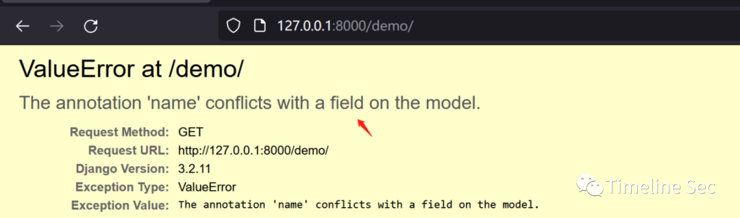
CVE-2022-28346:Django SQL注入漏洞
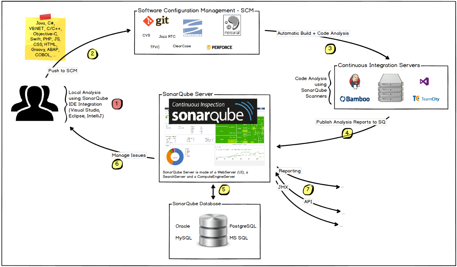
Play sonar
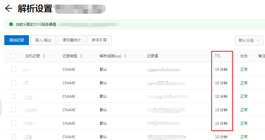
DNS series (I): why does the updated DNS record not take effect?
12.RNN应用于手写数字识别
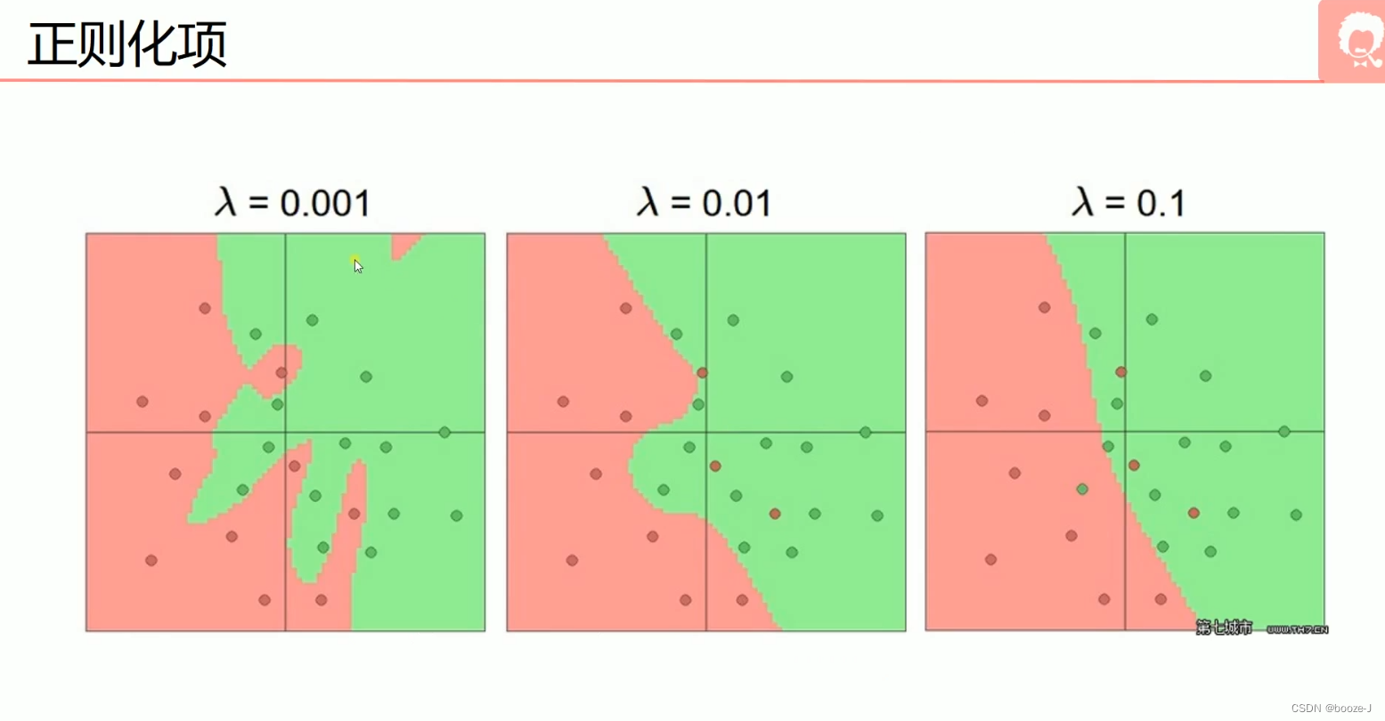
5.过拟合,dropout,正则化
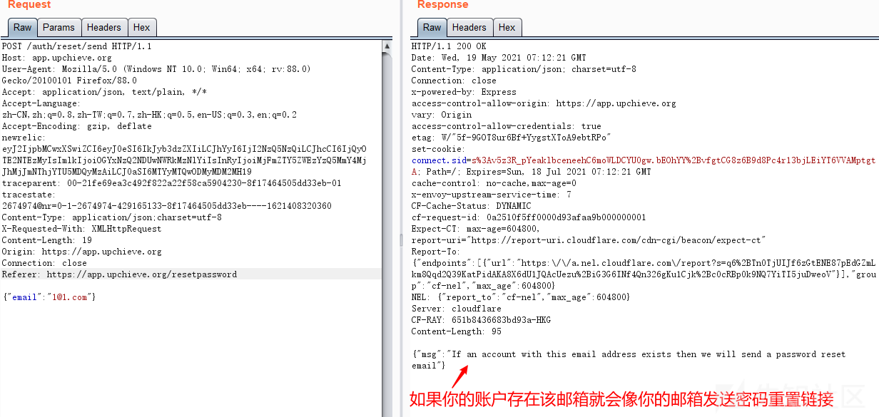
Password recovery vulnerability of foreign public testing
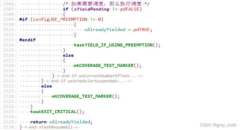
1293_ Implementation analysis of xtask resumeall() interface in FreeRTOS
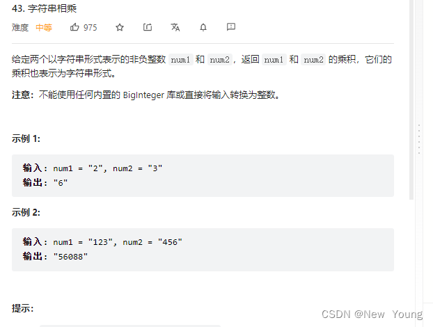
Letcode43: string multiplication
2022-07-07: the original array is a monotonic array with numbers greater than 0 and less than or equal to K. there may be equal numbers in it, and the overall trend is increasing. However, the number

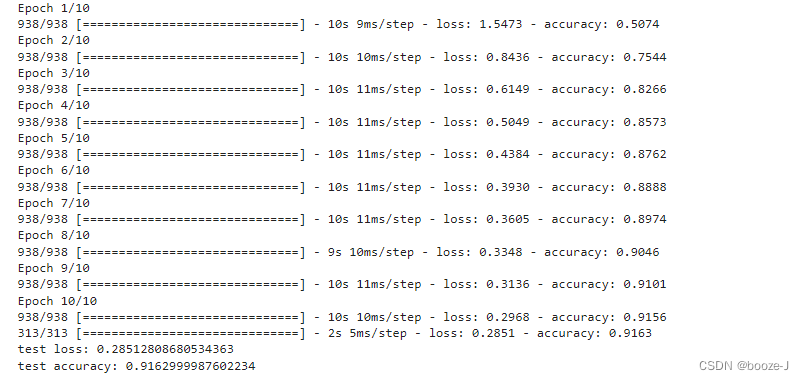
3.MNIST数据集分类
随机推荐
From starfish OS' continued deflationary consumption of SFO, the value of SFO in the long run
3 years of experience, can't you get 20K for the interview and test post? Such a hole?
股票开户免费办理佣金最低的券商,手机上开户安全吗
13. Model saving and loading
Service mesh introduction, istio overview
语义分割模型库segmentation_models_pytorch的详细使用介绍
How is it most convenient to open an account for stock speculation? Is it safe to open an account on your mobile phone
英雄联盟胜负预测--简易肯德基上校
丸子官网小程序配置教程来了(附详细步骤)
C # generics and performance comparison
9.卷积神经网络介绍
AI遮天传 ML-初识决策树
Analysis of 8 classic C language pointer written test questions
14.绘制网络模型结构
9. Introduction to convolutional neural network
Is it safe to speculate in stocks on mobile phones?
Lecture 1: the entry node of the link in the linked list
1293_FreeRTOS中xTaskResumeAll()接口的实现分析
Deep dive kotlin collaboration (the end of 23): sharedflow and stateflow
DNS series (I): why does the updated DNS record not take effect?