当前位置:网站首页>Learning record: Tim - Basic timer
Learning record: Tim - Basic timer
2022-07-06 15:33:00 【Bitter tea seeds】
Catalog
1.1、 Basic timer function block diagram explanation
1.6、 Calculation of timing time
2.1、 General timer Introduction
2.3、STM32 The general register of
3、 ... and 、 Steps to implement the program
3.1、 Basic timer implementation program steps
3.2、 Basic timer experimental phenomenon
3.3、 General timer implementation program steps
3.4、 General timer experimental phenomenon
Preface
Timer classification
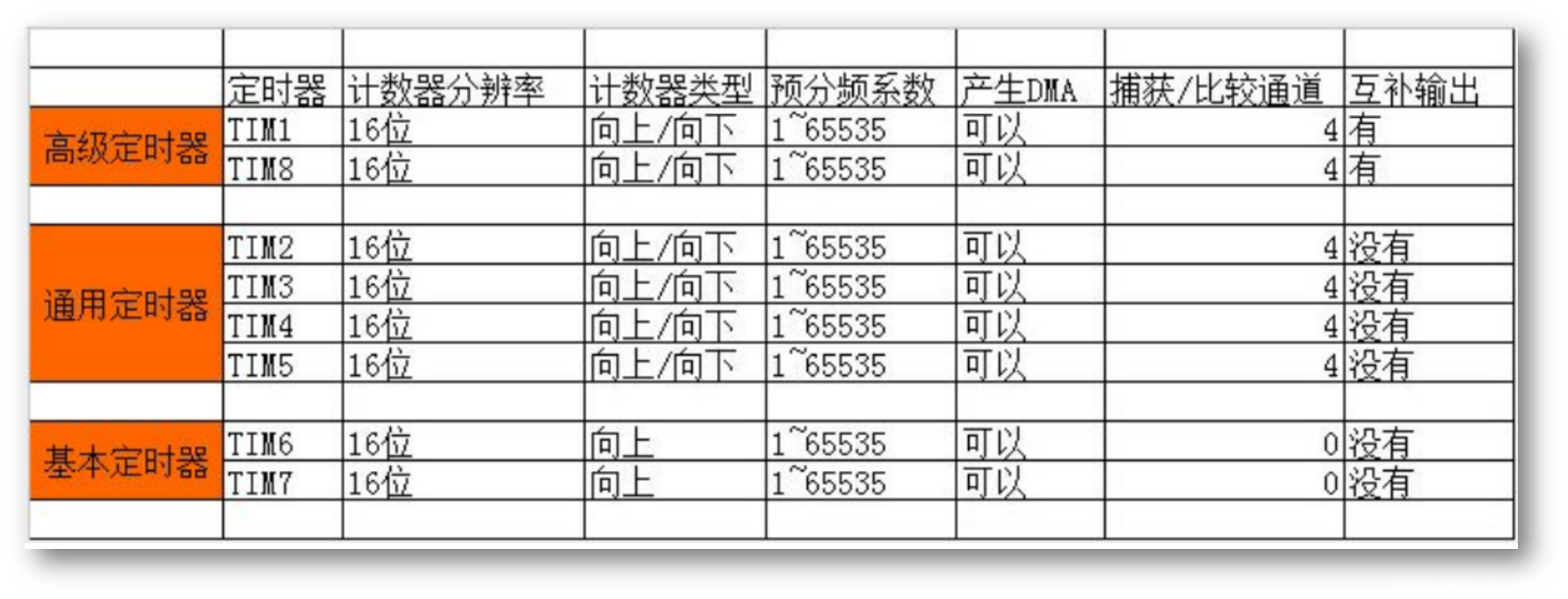
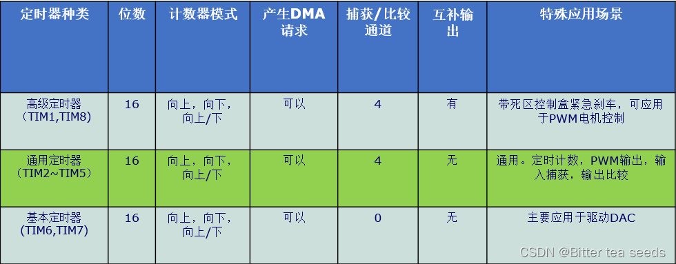
STM32F1 In the series , In addition to connected products , share 8 A timer , Divided into basic timers , Universal timer and advanced timer .
Basic timer TIM6 and TIM7 It's a 16 A timer that can only count up , It can only be timed , No external IO.
Universal timer TIM2、3、4、5 It's a 16 You can go up / The next timer to count , It can be timed , Can output comparison , You can enter capture , Each timer has four external IO.
Advanced timer TIM1、8 It's a 16 You can go up / The next timer to count , It can be timed , Can output comparison , You can enter capture , There can also be three-phase motor complementary output signal , Each timer has 8 External IO.
One 、STM32 Basic timer
1.1、 Basic timer function block diagram explanation
The core of the basic timer is Time base , Not only are the basic timers , General timer and advanced timer also have .
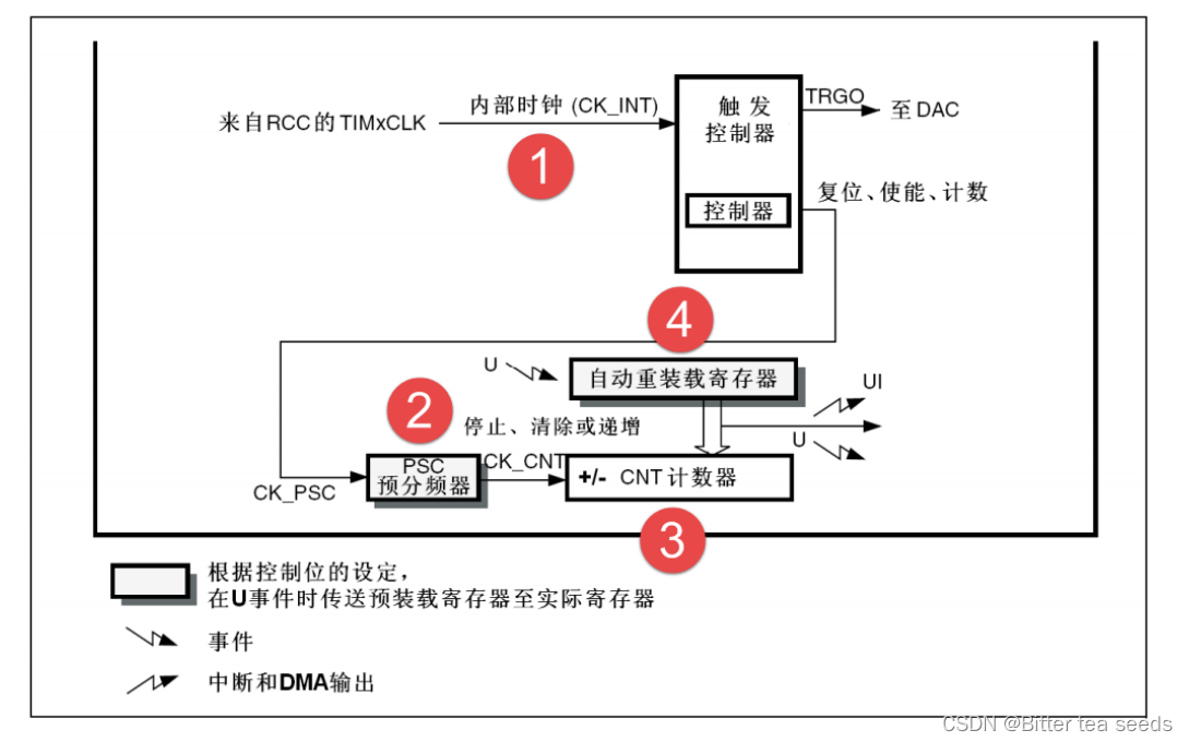
The main part of programmable general timer is a 16 Bit counter and its associated autoload register . This counter can count up 、 Count down or count up and down in both directions . The counter clock is divided by prescaler . Counter 、 The automatic loading register and prescaler register can be read and written by software , While the counter is running, it can still read and write .
The time base unit contains :
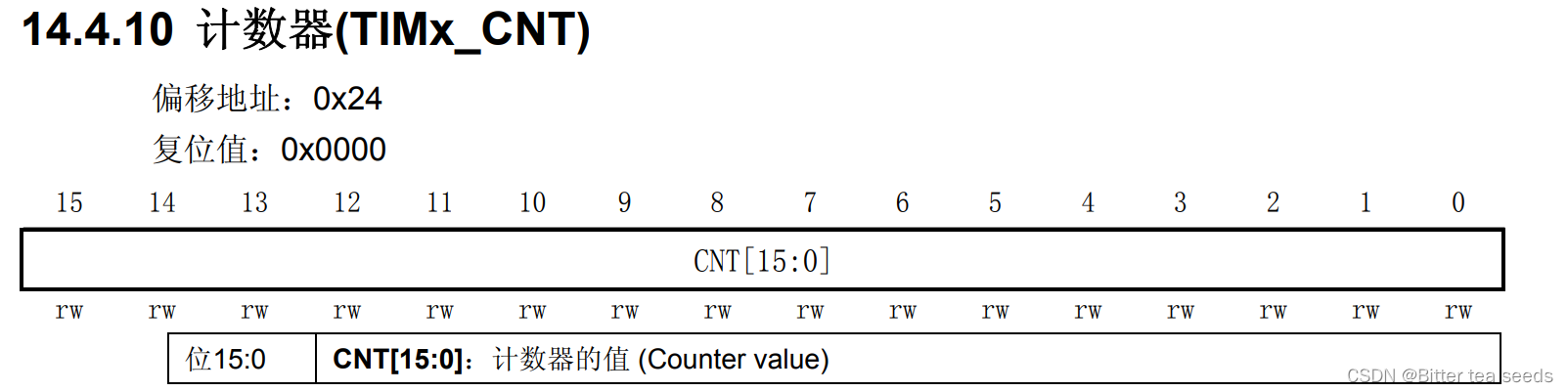
● Counter register (TIMx_CNT)
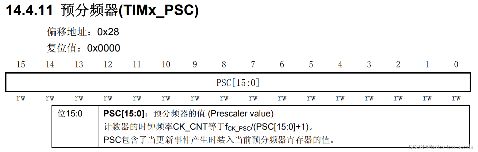
● Prescaler register (TIMx_PSC)
● Auto load registers (TIMx_ARR)
1.2、 Clock source
Timer clock TIMxCLK, The internal clock CK_INT, the APB1 The prescaler provides , If APB1 prescale The coefficient is equal to 1, Then the frequency does not change , Otherwise, the frequency is multiplied by 2, Library function APB1 The coefficient of the prescaler is 2, namely PCLK1=36M, therefore Timer clock TIMxCLK=36*2=72M.
1.3、 Counter clock
The timer clock goes by PSC Preassigned frequency counter after , namely CK_CNT, Used to drive the counter to count .PSC It's a 16 Bit prescaler , You can set the timer clock TIMxCLK Conduct 1~65536 Any number between them . Specific calculation method by :CK_CNT=TIMxCLK/(PSC+1).
1.4、 Counter
Counter CNT It's a 16 Bit counter , You can only count up , The maximum count is 65535. An update event is generated when the count reaches the auto reload register , And clear, count from the beginning .
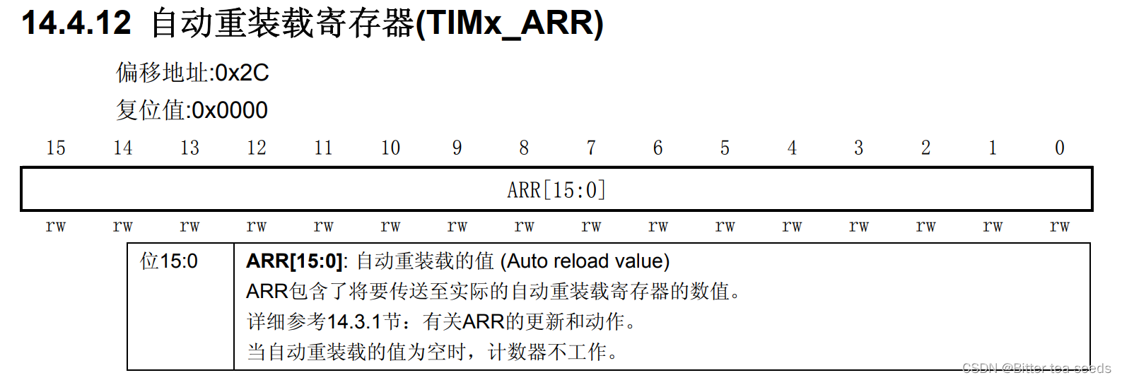
1.5、 Auto reload register
Auto reload register ARR It's a 16 Bit register , It's got the maximum number that a counter can count . When the count reaches this value , If interruption is enabled , The timer generates an overflow interrupt .
1.6、 Calculation of timing time
Timer The timing time is equal to the interrupt period of the counter multiplied by the number of interrupts . The counter is in CK_CNT Driven by , Count one The number of times is CK_CLK Reciprocal , be equal to :1/(TIMxCLK/(PSC+1)), The time to generate an interrupt is equal to : 1/(CK_CLK * ARR). If you set a variable in the interrupt service program time, Used to record the number of interrupts , Then we can calculate that the timing time we need is equal to :1/CK_CLK* (ARR+1)*time.
Two 、STM32 Universal timer
2.1、 General timer Introduction
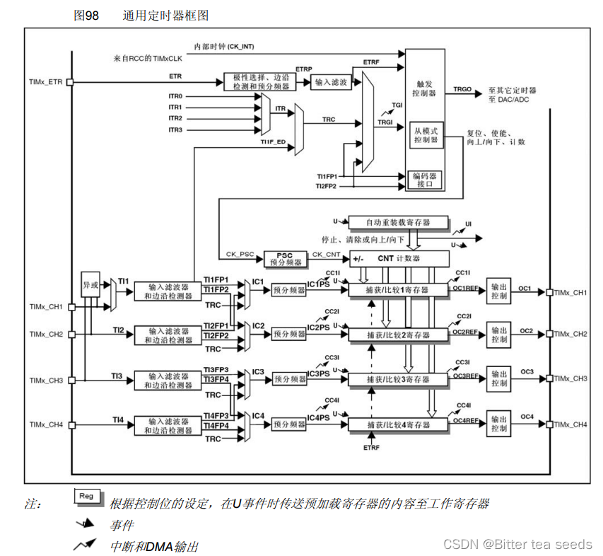
STM32F1 The universal timer of is a adopt Programmable prescaler (PSC) Driven 16 Bit auto loading counter (CNT) constitute .
STM32 A universal timer can be used for : Measure the pulse length of the input signal ( Input capture ) Or produce an output waveform ( Output comparison and PWM) etc. . Use a timer prescaler and RCC Clock controller prescaler , Pulse length and waveform period can be adjusted from a few microseconds to a few milliseconds .
STM32 Each universal timer is completely independent , There are no resources shared with each other .
2.2、TIMx The main function
Universal TIMx (TIM2、TIM3、TIM4 and TIM5) Timer functions include :
● 16 Position up 、 Down 、 Up / Down Auto load counter
Auto reload register ARR It's a 16 Bit register , It's got the maximum number that a counter can count . When you count to When it's worth it , If interruption is enabled , The timer generates an overflow interrupt .
● 16 position A programmable ( It can be modified in real time ) Preassigned frequency counter , The frequency division coefficient of the counter clock frequency is 1~65536 In between The number
● 4 individual Independent channel :
─ Input capture
─ Output comparison
─ PWM Generate ( Edge or center alignment mode )
─ Monopulse mode output
● Use The external signal controls the timer and the synchronization circuit interconnected with the timer
● The following events occur interrupt /DMA:
─ to update : The counter overflows up / Spilling down , Counter initialization ( Through software or internal / External trigger )
─ Triggering event ( The counter starts 、 stop it 、 Initialized or internally / External trigger count )
─ Input capture
─ Output comparison
● Support positioning The incremental ( orthogonal ) Encoder and Hall sensor circuits
● Trigger input as an external clock or current management by cycle
2.3、STM32 The general register of
Control register 1(TIMx_CR1)
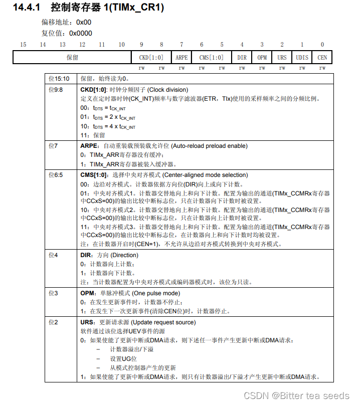
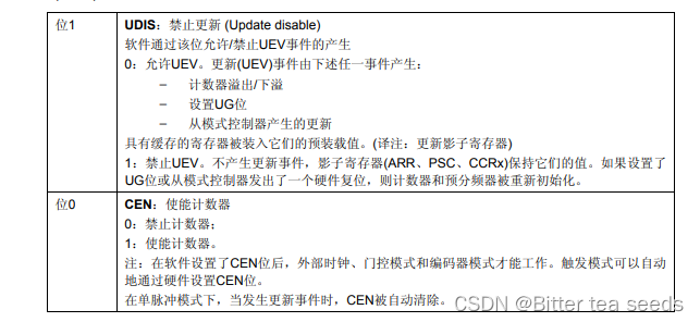
TIMx_CR1 The lowest point of , That is, the counter enable bit , This bit must be set to 1, To get the timer to start counting .
From 4 position DIR It can be seen that the default counting method is counting up , You can also count down .
The first 5,6 Bit is used to set the count alignment .
The first 8 And the 9 Bit can see , You can set the clock division factor of the timer to 1,2,4.
DMA/ Interrupt enable register (TIMx_DIER), The register is a 16 Bit register .
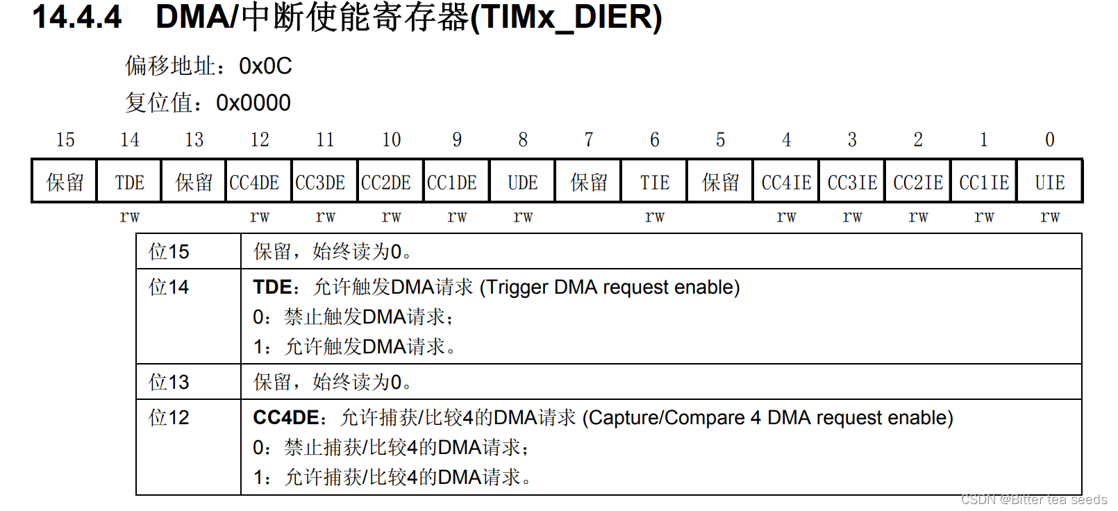
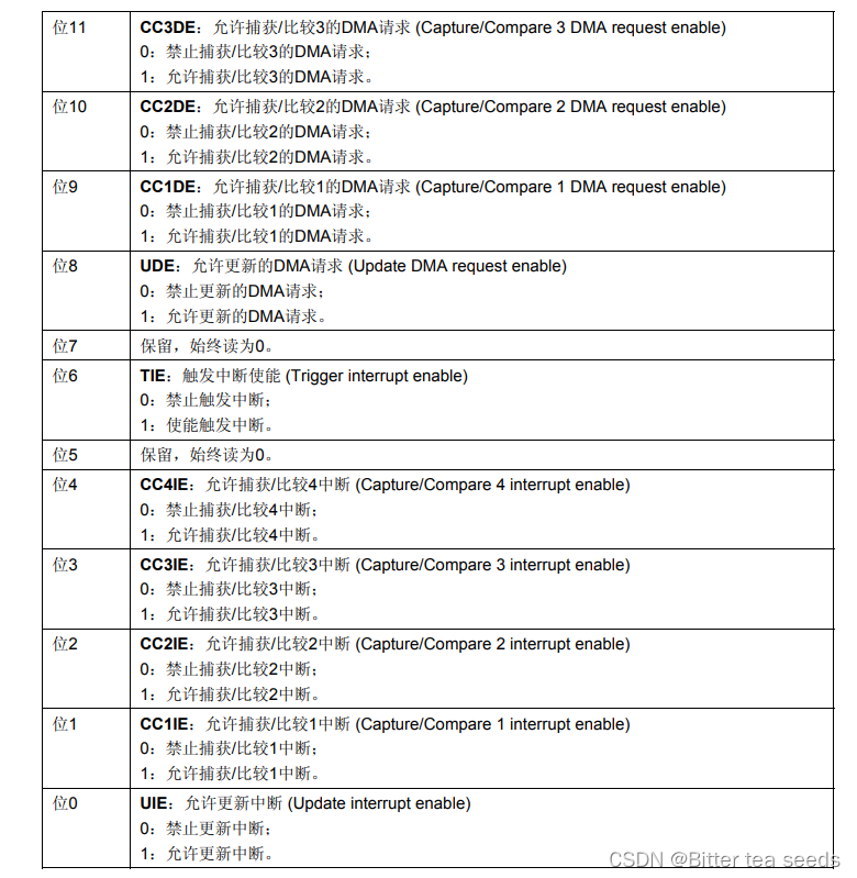
It's the first 0 position , This bit is the update interrupt allowed bit , The timer update interrupt is used , So this bit should be set to 1, To allow interrupts due to update Events .
Prescaler register (TIMx_PSC), This register divides the clock by setting , Then provide it to the counter , As a counter clock .
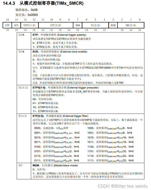
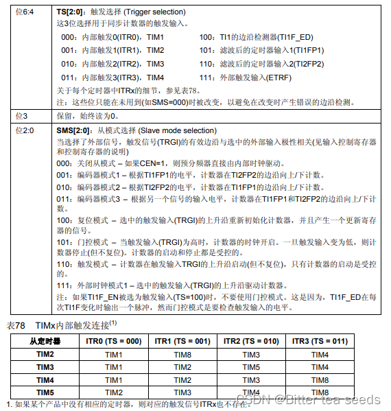
adopt TIMx_SMCR Register to set the clock :1. Internal clock (CK_INT)2. External clock mode 1: External input pins (TIx)3. External clock mode 2: External trigger input (ETR)4. Internal trigger input (ITRx): Use A Timer as B Timer prescaler (A by B Provide clock ).
there CK_INT The clock is from APB1 Double frequency , Unless APB1 Set the number of clock dividers to 1, Otherwise, the universal timer TIMx The clock is APB1 Of the clock 2 times , When APB1 When the clock doesn't divide , Universal timer TIMx The clock is equal to APB1 The clock of . It should also be noted that the clock of the advanced timer does not come from APB1, But from APB2 Of .
TIMx_CNT register , This register is the counter of the timer , This register stores the count value of the current timer .
Auto reload register (TIMx_ARR) Physically, it actually corresponds to 2 A register . One is that programmers can operate directly , The other is the shadow register .
What really works is the shadow register . according to TIMx_CR1 register in APRE Bit setting :APRE=0 when , The contents of the preloaded register can be transferred to the shadow register at any time , here 2 The is connected ; and APRE=1 when , At each update event (UEV) when , Just transfer the contents pre installed in the register to the shadow register .
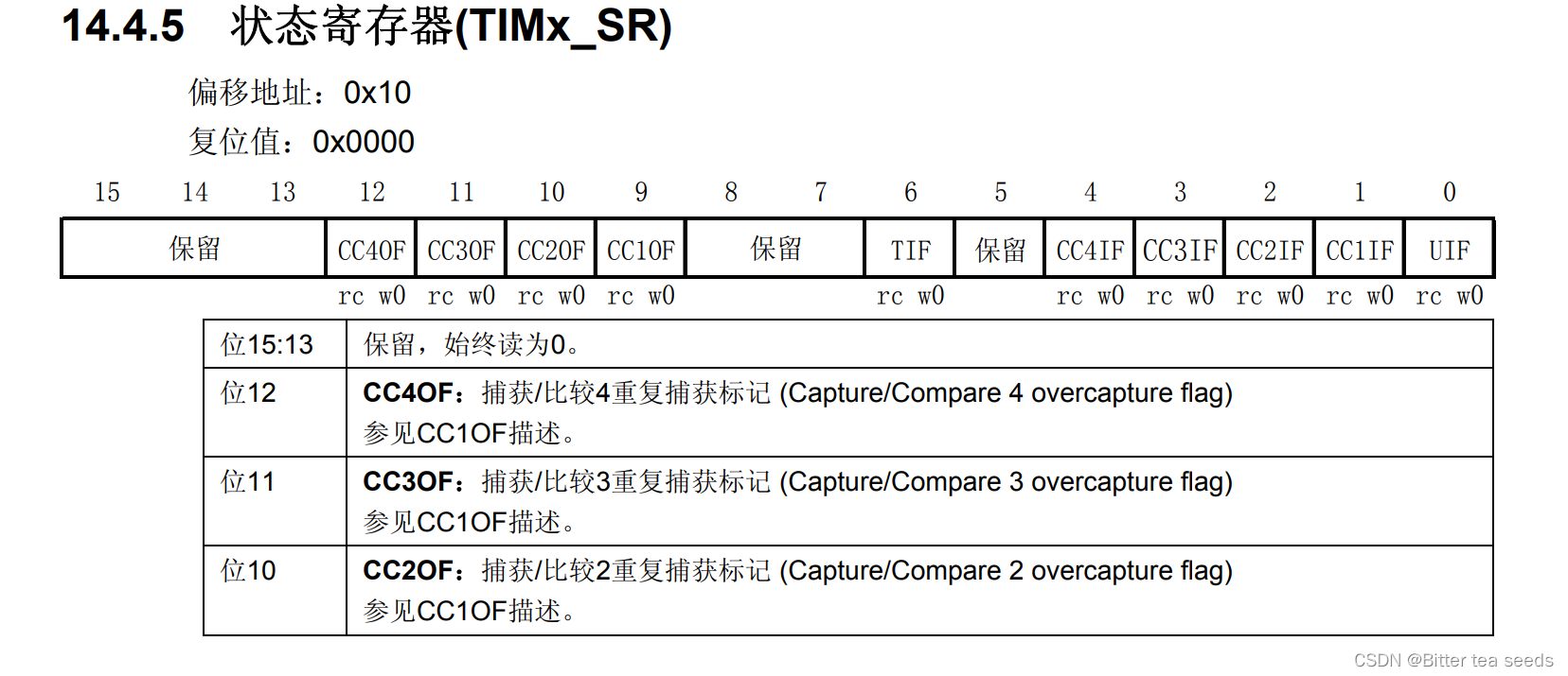
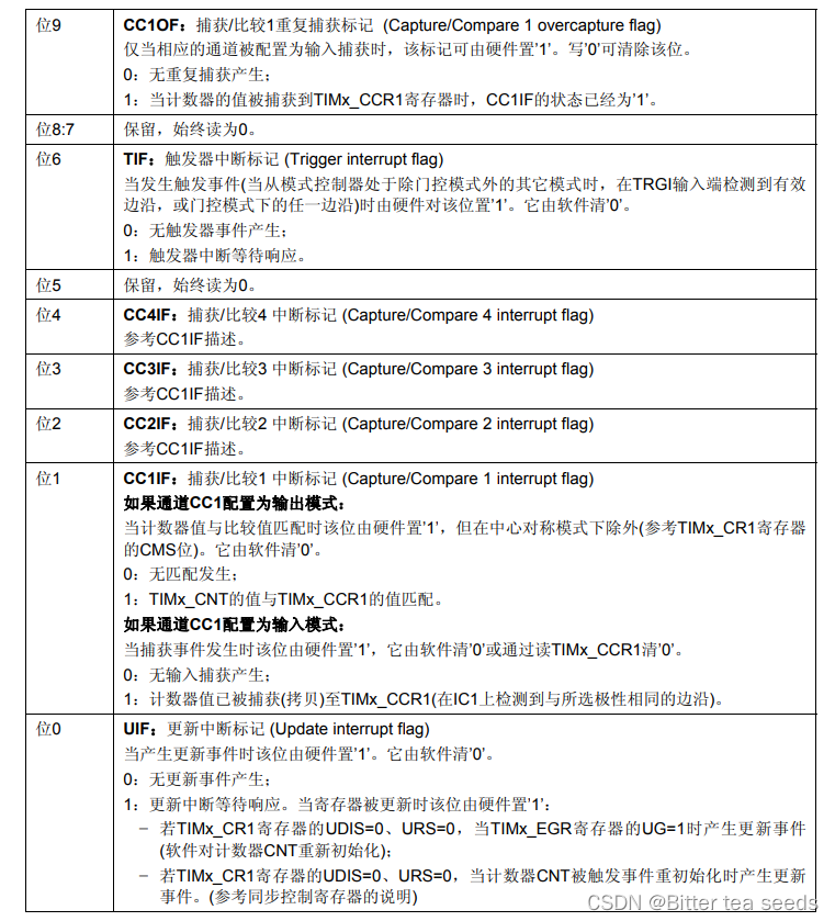
Status register (TIMx_SR) It is used to mark various events related to the current timer / Whether the interruption occurs .
3、 ... and 、 Steps to implement the program
Use timer to generate interrupt , Then flip in the interrupt service function DS1 The level on the , To indicate the generation of timer interrupt .
3.1、 Basic timer implementation program steps
(1) TIM_Prescaler: Timer prescaler settings , The clock source is the timer clock through the prescaler , It sets TIMx_PSC Register value . The settable range is 0 to 65535, Realization 1 to 65536 frequency division .
(2) TIM_CounterMode: Timer counting mode , But counting up for 、 Down counting and three center alignment patterns . The basic timer can only count up , namely TIMx_CNT Only from 0 Began to increase , And there's no need to initialize .
(3) TIM_Period: Timer cycle , It's actually setting the value of the auto overload register , Update to shadow mail when the event is generated Memory . The settable range is 0 to 65535.
(4) TIM_ClockDivision: The clock frequency division , Set the timer clock CK_INT The frequency is divided by the sampling clock frequency of the digital filter Frequency ratio , The basic timer doesn't have this function , No settings .
(5) TIM_RepetitionCounter: Repeat counter , It belongs to special register bit of advanced control register , It is very easy to control the output PWM The number of . There's no need to set up .
LED.h The code is as follows :
#ifndef __LED_H
#define	__LED_H


#include "stm32f10x.h"


/*  Definition LED Connected GPIO port ,  The user only needs to modify the following code to change the control LED Pin  */
// R- Red
#define LED1_GPIO_PORT    	GPIOB			              /* GPIO port  */
#define LED1_GPIO_CLK 	    RCC_APB2Periph_GPIOB		/* GPIO Port clock  */
#define LED1_GPIO_PIN		GPIO_Pin_5			        /*  Connect to SCL Clock line GPIO */

#define ON  0
#define OFF 1

/*  Use standard firmware library to control IO*/
#define LED1(a)	if (a)	\
					GPIO_SetBits(LED1_GPIO_PORT,LED1_GPIO_PIN);\
					else		\
					GPIO_ResetBits(LED1_GPIO_PORT,LED1_GPIO_PIN)


/*  The method of directly operating registers controls IO */
#define	digitalHi(p,i)		 {p->BSRR=i;}	 // The output is high level
#define digitalLo(p,i)		 {p->BRR=i;}	 // Output low level
#define digitalToggle(p,i) {p->ODR ^=i;} // Output reverse state


/*  Define control IO The macro  */
#define LED1_TOGGLE		 digitalToggle(LED1_GPIO_PORT,LED1_GPIO_PIN)
#define LED1_OFF		   digitalHi(LED1_GPIO_PORT,LED1_GPIO_PIN)
#define LED1_ON			   digitalLo(LED1_GPIO_PORT,LED1_GPIO_PIN)

void LED_GPIO_Config(void);

#endif /* __LED_H */
LED.c The procedure is as follows :
#include "bsp_led.h"


void LED_GPIO_Config(void)
{
		/* Define a GPIO_InitTypeDef Type of structure */
		GPIO_InitTypeDef GPIO_InitStructure;

		/* Turn on LED dependent GPIO Peripheral clock */
		RCC_APB2PeriphClockCmd( LED1_GPIO_CLK , ENABLE);

		/* Choose what you want to control GPIO Pin */
		GPIO_InitStructure.GPIO_Pin = LED1_GPIO_PIN;

		/* Set pin mode to universal push pull output */
		GPIO_InitStructure.GPIO_Mode = GPIO_Mode_Out_PP;

		/* Set the pin rate to 50MHz */
		GPIO_InitStructure.GPIO_Speed = GPIO_Speed_50MHz;

		/* Call library function , initialization GPIO*/
		GPIO_Init(LED1_GPIO_PORT, &GPIO_InitStructure);

		/*  Close all led The lamp 	*/
		GPIO_SetBits(LED1_GPIO_PORT, LED1_GPIO_PIN);

}
TIMEBASE.h The procedure is as follows :
#ifndef __BSP_TIMEBASE_H
#define __BSP_TIMEBASE_H


#include "stm32f10x.h"

#define BASIC_TIM6 //  If you use TIM7, Comment out this macro

#ifdef  BASIC_TIM6 //  Use the basic timer TIM6
#define            BASIC_TIM                   TIM6
#define            BASIC_TIM_APBxClock_FUN     RCC_APB1PeriphClockCmd
#define            BASIC_TIM_CLK               RCC_APB1Periph_TIM6
#define            BASIC_TIM_Period            (1000-1)
#define            BASIC_TIM_Prescaler         71
#define            BASIC_TIM_IRQ               TIM6_IRQn
#define            BASIC_TIM_IRQHandler        TIM6_IRQHandler

#else  //  Use the basic timer TIM7
#define            BASIC_TIM                   TIM7
#define            BASIC_TIM_APBxClock_FUN     RCC_APB1PeriphClockCmd
#define            BASIC_TIM_CLK               RCC_APB1Periph_TIM7
#define            BASIC_TIM_Period            1000-1
#define            BASIC_TIM_Prescaler         71
#define            BASIC_TIM_IRQ               TIM7_IRQn
#define            BASIC_TIM_IRQHandler        TIM7_IRQHandler

#endif

void BASIC_TIM_Init(void);


#endif	/* __BSP_TIMEBASE_H */
TIMEBASE.c The procedure is as follows :
//  Basic timer TIMx,x[6,7] Timing initialization function
#include "bsp_TiMbase.h"

//  Interrupt priority configuration
static void BASIC_TIM_NVIC_Config(void)
{
    NVIC_InitTypeDef NVIC_InitStructure;
    //  Set the interrupt group to 0
    NVIC_PriorityGroupConfig(NVIC_PriorityGroup_0);
		//  Set the interrupt source
    NVIC_InitStructure.NVIC_IRQChannel = BASIC_TIM_IRQ ;
		//  Set the primary priority to  0
    NVIC_InitStructure.NVIC_IRQChannelPreemptionPriority = 0;
	  //  Set preemption priority to 3
    NVIC_InitStructure.NVIC_IRQChannelSubPriority = 3;
    NVIC_InitStructure.NVIC_IRQChannelCmd = ENABLE;
    NVIC_Init(&NVIC_InitStructure);
}

/*
 *  Be careful :TIM_TimeBaseInitTypeDef Inside the structure are 5 Members ,TIM6 and TIM7 There are only
 * TIM_Prescaler and TIM_Period, So use TIM6 and TIM7 You just need to initialize these two members ,
 *  The other three members are general timer and advanced timer .
 *-----------------------------------------------------------------------------
 *typedef struct
 *{ TIM_Prescaler             There are
 *	TIM_CounterMode			     TIMx,x[6,7] No, , Everything else has
 *  TIM_Period                There are
 *  TIM_ClockDivision        TIMx,x[6,7] No, , Everything else has
 *  TIM_RepetitionCounter    TIMx,x[1,8,15,16,17] Only then
 *}TIM_TimeBaseInitTypeDef;
 *-----------------------------------------------------------------------------
 */


static void BASIC_TIM_Mode_Config(void)
{
    TIM_TimeBaseInitTypeDef  TIM_TimeBaseStructure;

		//  Turn on the timer clock , The internal clock CK_INT=72M
    BASIC_TIM_APBxClock_FUN(BASIC_TIM_CLK, ENABLE);

		//  Automatically reload the value of the register , Cumulative TIM_Period+1 Generate an update or interrupt after a frequency
    TIM_TimeBaseStructure.TIM_Period = BASIC_TIM_Period;

	  //  The prescaled frequency of the clock is
    TIM_TimeBaseStructure.TIM_Prescaler= BASIC_TIM_Prescaler;

		//  Clock division factor  , The basic timer doesn't have , Never mind
    //TIM_TimeBaseStructure.TIM_ClockDivision=TIM_CKD_DIV1;

		//  Counter counting mode , The basic timer can only count up , There is no setting for counting mode
    //TIM_TimeBaseStructure.TIM_CounterMode=TIM_CounterMode_Up;

		//  Repeat counter value , The basic timer doesn't have , Never mind
		//TIM_TimeBaseStructure.TIM_RepetitionCounter=0;

	  //  Initialize the timer
    TIM_TimeBaseInit(BASIC_TIM, &TIM_TimeBaseStructure);

		//  Clear Counter interrupt flag bit
    TIM_ClearFlag(BASIC_TIM, TIM_FLAG_Update);

		//  Turn on Counter interrupt
    TIM_ITConfig(BASIC_TIM,TIM_IT_Update,ENABLE);

		//  Enable counter
    TIM_Cmd(BASIC_TIM, ENABLE);
}

void BASIC_TIM_Init(void)
{
	BASIC_TIM_NVIC_Config();
	BASIC_TIM_Mode_Config();
}
main.c The procedure is as follows :
//  Basic timer TIMx,x[6,7] Timed application
#include "stm32f10x.h"
#include "bsp_led.h"
#include "bsp_TiMbase.h"

volatile uint32_t time = 0; // ms  Timing variables

int main(void)
{
	/* led  port configuration  */
	LED_GPIO_Config();

	BASIC_TIM_Init();

  while(1)
  {
    if ( time == 1000 ) /* 1000 * 1 ms = 1s  Time out  */
    {
      time = 0;
			/* LED1  Take the opposite  */
			LED1_TOGGLE;
    }
  }
}
3.2、 Basic timer experimental phenomenon
Punctual atomic elite development board LED0 The red light flashes every second ;
3.3、 General timer implementation program steps
time.h The procedure is as follows :
#ifndef __TIMER_H
#define __TIMER_H
#include "sys.h"

void TIM3_Int_Init(u16 arr,u16 psc);

#endif
time.c The procedure is as follows :
#include "timer.h"
#include "led.h"

// Universal timer 3 Interrupt initialization
// Here, the clock is selected as APB1 Of 2 times , and APB1 by 36M
//arr: Auto reload value .
//psc: Clock presplitting frequency
// Here's a timer 3!
void TIM3_Int_Init(u16 arr,u16 psc)
{
    TIM_TimeBaseInitTypeDef  TIM_TimeBaseStructure;
	NVIC_InitTypeDef NVIC_InitStructure;

	RCC_APB1PeriphClockCmd(RCC_APB1Periph_TIM3, ENABLE); // Clock enable

	// Timer TIM3 initialization
	TIM_TimeBaseStructure.TIM_Period = arr; // Set the value of the auto reload register cycle for the next update event load activity
	TIM_TimeBaseStructure.TIM_Prescaler =psc; // Set as TIMx Prescaled value of clock frequency divisor
	TIM_TimeBaseStructure.TIM_ClockDivision = TIM_CKD_DIV1; // Set the clock split :TDTS = Tck_tim
	TIM_TimeBaseStructure.TIM_CounterMode = TIM_CounterMode_Up;  //TIM Upcount mode
	TIM_TimeBaseInit(TIM3, &TIM_TimeBaseStructure); // Initialize... According to the specified parameters TIMx Unit of time base

	TIM_ITConfig(TIM3,TIM_IT_Update,ENABLE ); // Enable to designate TIM3 interrupt , Allow update interrupt

	// Interrupt priority NVIC Set up
	NVIC_InitStructure.NVIC_IRQChannel = TIM3_IRQn;  //TIM3 interrupt
	NVIC_InitStructure.NVIC_IRQChannelPreemptionPriority = 0;  // Take precedence 0 level
	NVIC_InitStructure.NVIC_IRQChannelSubPriority = 3;  // From the priority 3 level
	NVIC_InitStructure.NVIC_IRQChannelCmd = ENABLE; //IRQ The channel is energized
	NVIC_Init(&NVIC_InitStructure);  // initialization NVIC register


	TIM_Cmd(TIM3, ENABLE);  // Can make TIMx
}
// Timer 3 Interrupt service routine
void TIM3_IRQHandler(void)   //TIM3 interrupt
{
	if (TIM_GetITStatus(TIM3, TIM_IT_Update) != RESET)  // Check TIM3 Whether the update interrupt occurs or not
		{
		TIM_ClearITPendingBit(TIM3, TIM_IT_Update  );  // eliminate TIMx Update interrupt flag
		LED1=!LED1;
		}
}
main.c The procedure is as follows
#include "led.h"
#include "delay.h"
#include "key.h"
#include "sys.h"
#include "usart.h"
#include "timer.h"


 int main(void)
 {

	delay_init();	    	 // Delay function initialization
	NVIC_PriorityGroupConfig(NVIC_PriorityGroup_2); // Set up NVIC Interrupt grouping 2:2 Bit preemption priority ,2 Bit response priority
	uart_init(115200);	 // The serial port is initialized to 115200
 	LED_Init();			     //LED Port initialization
	TIM3_Int_Init(4999,7199);//10Khz The counting frequency of , Count to 5000 by 500ms
   	while(1)
	{
		LED0=!LED0;
		delay_ms(200);
	}


}
3.4、 General timer experimental phenomenon
Punctual atomic elite development board LED0 The red light flashes more than LED1 The green light is fast ;
边栏推荐
- Jupyter installation and use tutorial
- Future trend and planning of software testing industry
- ucorelab3
- Eigen User Guide (Introduction)
- CSAPP Shell Lab 实验报告
- STM32学习记录:输入捕获应用
- Crawler series of learning while tapping (3): URL de duplication strategy and Implementation
- 線程及線程池
- LeetCode#268. Missing numbers
- 安全测试入门介绍
猜你喜欢
STM32学习记录:LED灯闪烁(寄存器版)
UCORE lab8 file system experiment report
What if software testing is too busy to study?
Servlet

Crawler series of learning while tapping (3): URL de duplication strategy and Implementation
Jupyter installation and use tutorial
CSAPP Shell Lab 实验报告
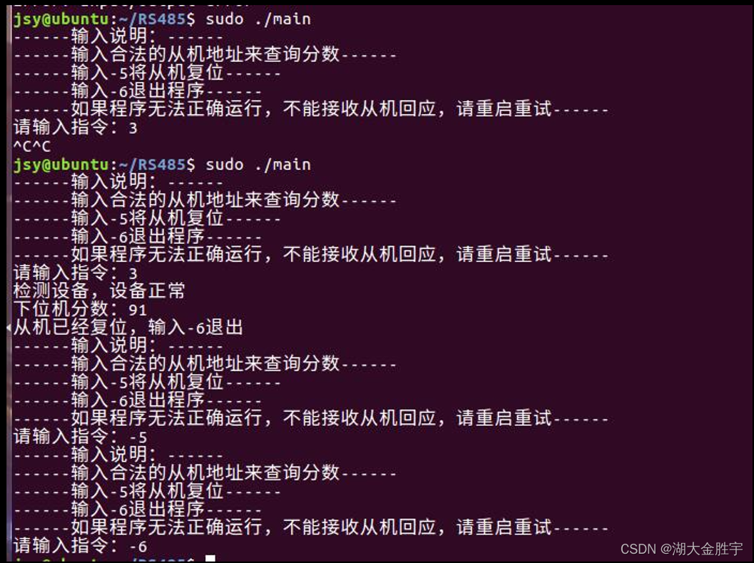
Scoring system based on 485 bus
How to become a good software tester? A secret that most people don't know
Video scrolling subtitle addition, easy to make with this technique

随机推荐
LeetCode#2062. Count vowel substrings in strings
Cadence physical library lef file syntax learning [continuous update]
Your wechat nickname may be betraying you
Automated testing problems you must understand, boutique summary
ArrayList集合
UCORE LaB6 scheduler experiment report
Eslint--- error: newline required at end of file but not found (EOL last) solution
Mysql database (IV) transactions and functions
STM32 learning record: input capture application
Sorting odd and even subscripts respectively for leetcode simple problem
Research Report on market supply and demand and strategy of China's medical chair industry
软件测试方法有哪些?带你看点不一样的东西
Want to change jobs? Do you know the seven skills you need to master in the interview software test
Brief introduction to libevent
JS --- all basic knowledge of JS (I)
The wechat red envelope cover designed by the object is free! 16888
Contest3145 - the 37th game of 2021 freshman individual training match_ A: Prizes
pytest
学习记录:理解 SysTick系统定时器,编写延时函数
Example 071 simulates a vending machine, designs a program of the vending machine, runs the program, prompts the user, enters the options to be selected, and prompts the selected content after the use