当前位置:网站首页>STM32 learning record: input capture application
STM32 learning record: input capture application
2022-07-06 15:23:00 【Bitter tea seeds】
Catalog
One 、 Input capture application
1.1、 Measure pulse width or frequency
1.2、 Steps and methods of measuring frequency
1.3、 Steps and methods of measuring pulse width
2.1、CH1 For example , Input capture workflow
2.3、 Input filtering and edge detection
2.5、 Preassigned frequency counter
3、 ... and 、 Output comparison
3.1、 The function of output comparison
4.1、 Capture / Compare mode register :TIMx_CCMR1
4.2、 Capture / Compare enable register :TIMx_CCER
4.3、DMA/ Interrupt enable register :TIMx_DIER
Preface
Introduce the use of general timer as input capture . use TIM5 The passage of 1(PA0) For input capture , Capture PA0 Pulse width of upper high level ( use WK_UP Key in high level ), Print high-level pulse width time through serial port .
One 、 Input capture application
Input capture is generally used in two ways , One aspect is Pulse jump along time measurement , On the other hand PWM Input measurement .
The input capture mode can be used to measure pulse width or frequency .STM32 Timer for , except TIM6 and TIM7, Other timers have input capture functions .
STM32 Input capture for , Just by testing TIMx_CHx Edge signal on , At the edge, the signal jumps ( For example, the rising edge / Falling edge ) When , Set the current timer value (TIMx_CNT) The capture stored in the corresponding channel / Compare register (TIMx_CCRx) Inside , Complete a capture . At the same time, you can configure whether the interrupt is triggered when capturing /DMA .
be used TIM5_CH1 To capture high-level pulse width , That is, first set the input capture as rising edge detection , Record when the rising edge occurs TIM5_CNT Value . Then, the acquisition signal is configured as falling edge acquisition , When the descent edge comes , Occurrence capture , And record the TIM5_CNT value . such , Twice before and after TIM5_CNT The difference between the , High level pulse width , meanwhile TIM5 We know the counting frequency of , Thus, the accurate time of high-level pulse width can be calculated .
1.1、 Measure pulse width or frequency
1.2、 Steps and methods of measuring frequency
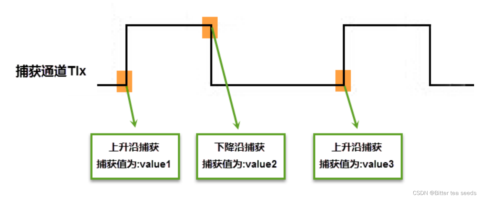
When capturing channels TIx When there is a rising edge on , The first capture happened , Counter CNT The value of is latched to the capture register CCR in , And there's also a capture interrupt , Record a capture in the interrupt service routine ( You can use a flag variable to record ), And read the value in the capture register to value1 in . When there is a second rising edge , A second capture occurred , Counter CNT The value of is latched to the capture register again CCR in , And enter capture interrupt again , In the capture interrupt , Read the value of the capture register to value3 in , And clear the capture record flag . utilize value3 and value1 We can calculate the period of the signal ( frequency ).
1.3、 Steps and methods of measuring pulse width
When capturing channels TIx When there is a rising edge on , The first capture happened , Counter CNT The value of is latched to the capture register CCR in , And there's also a capture interrupt , Record a capture in the interrupt service routine ( You can use a flag variable to record ), And read the value in the capture register to value1 in . Then change the capture edge to the falling edge , The purpose is to capture the trailing falling edge . When the falling edge comes , A second capture occurred , Counter CNT The value of is latched to the capture register again CCR in , And enter capture interrupt again , In the capture interrupt , Read the value of the capture register to value3 in , And clear the capture record flag . Then set the capture edge to the rising edge . In the process of measuring pulse width, we need to switch back and forth to capture the polarity of the edge , If the measured pulse duration is long , The timer will overflow , An update interrupt is generated when overflow occurs , We can record overflow in interrupt .
Two 、 Input capture workflow
2.1、CH1 For example , Input capture workflow
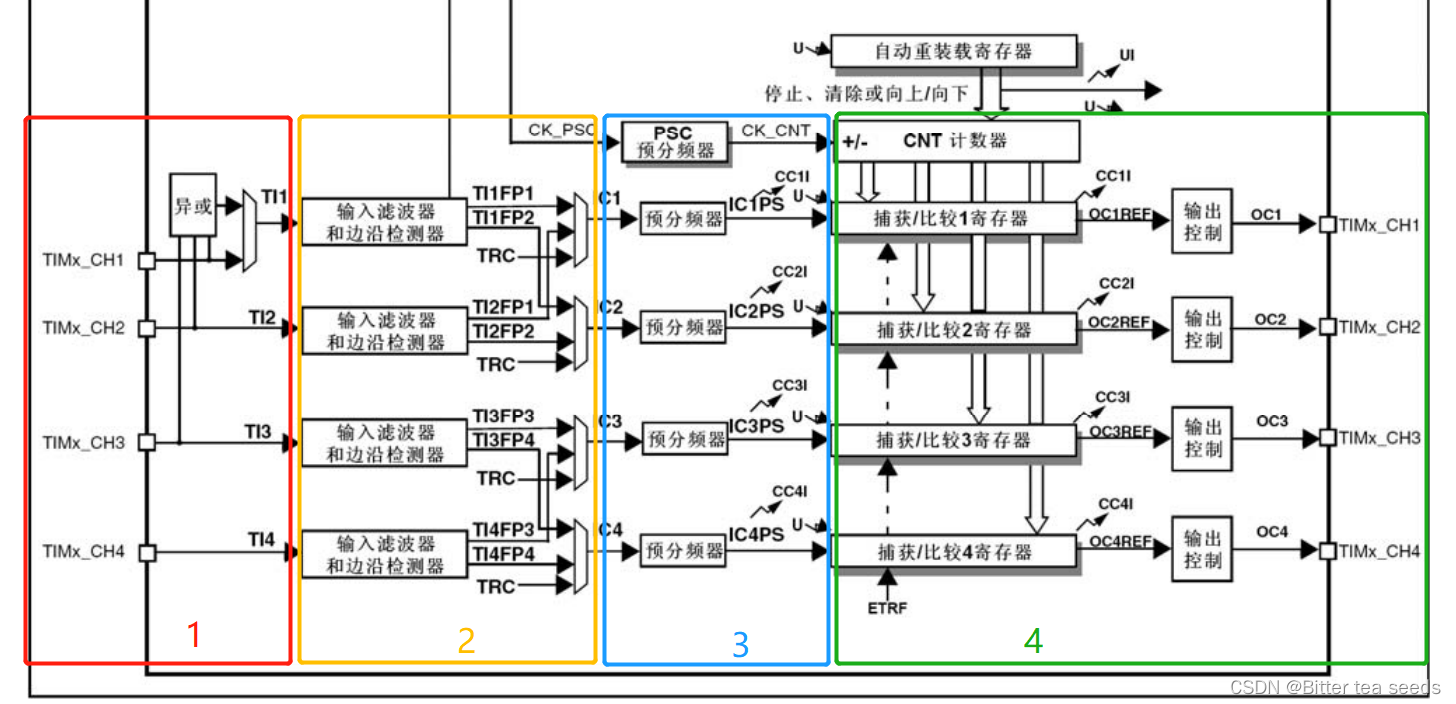
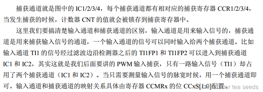
2.2、 Input channel
When using the signal to be measured from the external pin of the timer TIMx_CH1/2/3/4 Get into , Usually called TI1/2/3/4, In the later acquisition, the signal to be measured is represented by TIx It's the standard name .
2.3、 Input filtering and edge detection
2.4、 Capture channels
2.5、 Preassigned frequency counter
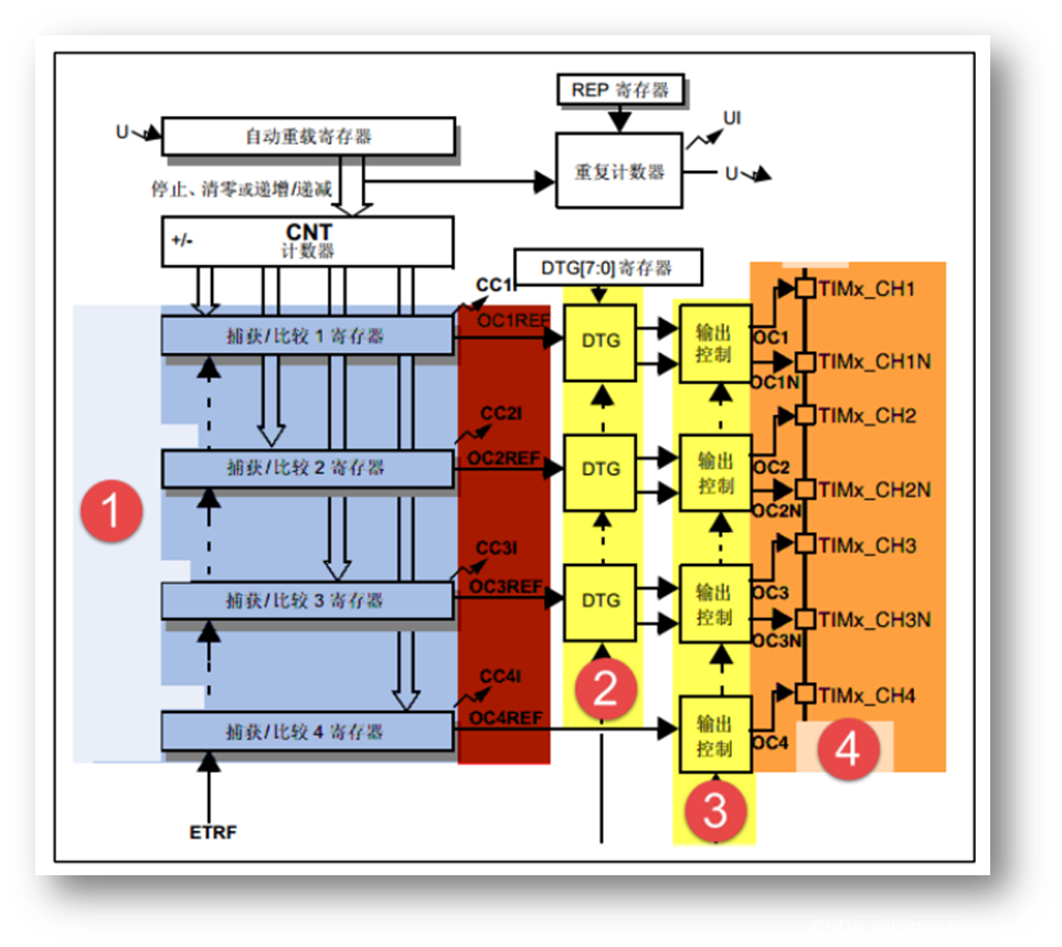
1、ICx The output of the signal goes through a prescaler , Used to capture once when deciding how many events occur .
2、 Specifically, the register CCMRx Bit ICxPSC To configure , If you want to capture every edge of the signal , No frequency division .
3、 ... and 、 Output comparison
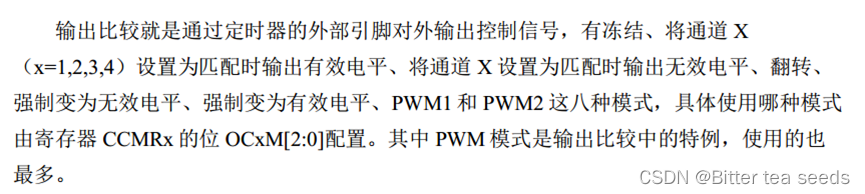
3.1、 The function of output comparison
Four 、 Capture register
The registers that need to be used are :TIMx_ARR、 TIMx_PSC、TIMx_CCMR1、TIMx_CCER、TIMx_DIER、TIMx_CR1、TIMx_CCR1 .
4.1、 Capture / Compare mode register :TIMx_CCMR1
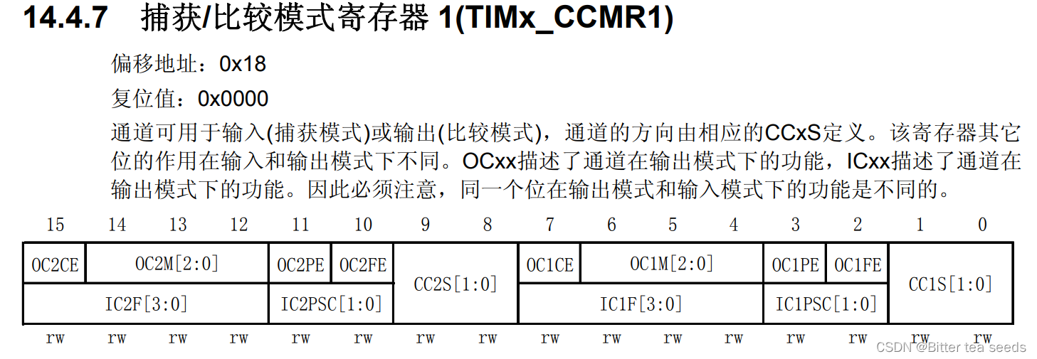 When used in input capture mode , Corresponding to the description in the second line , As you can see from the diagram ,TIMx_CCMR1 Obviously for 2 Configuration of channels , Lower eight [7:0] Used to capture / Compare channels 1 The control of , And high eight position [15:8] Is used to capture / Compare channels 2 The control of .
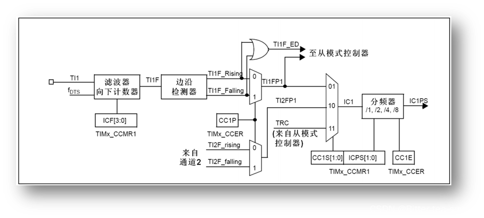
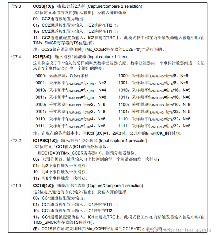 among CC1S[1:0], These two bits are used for CCR1 Channel configuration , Here we set IC1S[1:0]=01, That is to say Set up IC1 Map on TI1 On ;
Input capture 1 Preassigned frequency counter IC1PSC[1:0]; because 1 The secondary edge triggers 1 Time capture , So choose 00 .
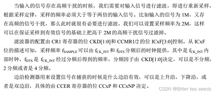
Input capture 1 filter IC1F[3:0], This is used to set the input sampling frequency and the length of the digital filter . among  Is the input frequency of the timer (TIMxCLK), It's usually 72Mhz. and
  It is based on TIMx_CR1 Of CKD[1:0] To determine the setting of , If CKD[1:0] Set to 00, that
  .N The value is the filter length , A simple example : hypothesis IC1F[3:0]=0011, And set up IC1 Map to channel 1 On , And it is triggered by the rising edge , So when you capture the rising edge , And then to The frequency of , Continuous sampling to 8 Secondary channel 1 The level of , If it's all high , It indicates that it is an effective trigger , An input capture interrupt is triggered ( If it's on ). This can filter out those high-level pulse width lower than 8 Pulse signal with sampling period , So as to achieve the effect of filtering .
4.2、 Capture / Compare enable register :TIMx_CCER
To use the lowest of this register 2 position ,CC1E and CC1P position .
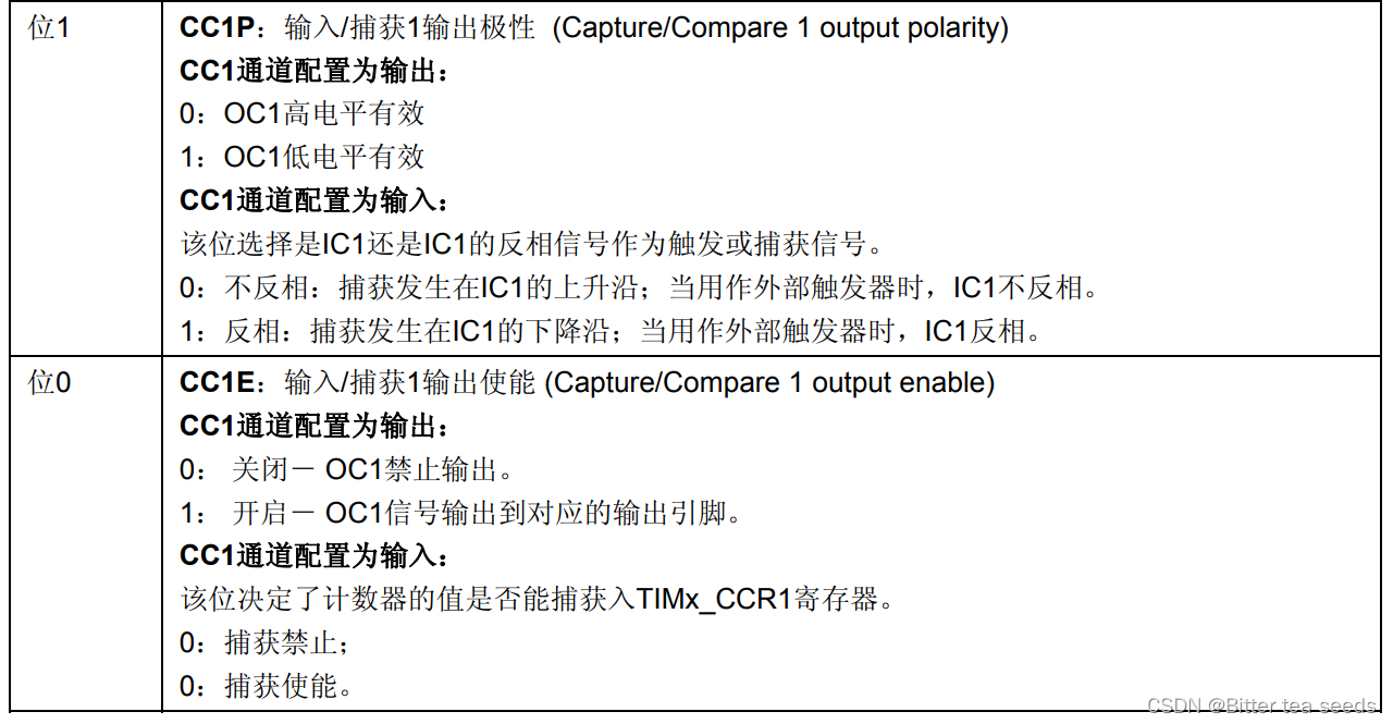
To enable input capture , You have to set CC1E=0, and CC1P Configure according to your own needs .
4.3、DMA/ Interrupt enable register :TIMx_DIER
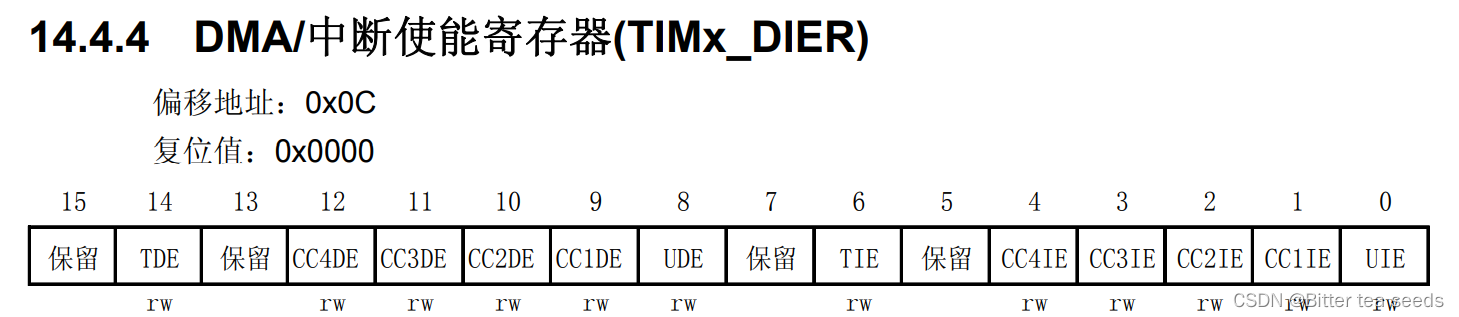
 Interrupts are needed to process captured data , So we have to open the channel 1 In the capture comparison of break , namely CC1IE Set to 1.
5、 ... and 、 Programming
5.1、 Configuration steps
① The initialization timer corresponds to the channel IO The clock of .
② initialization IO mouth , The mode is input :GPIO_Init();
GPIO_InitStructure.GPIO_Mode = GPIO_Mode_IPD; //PA0 Input
③ Initialize the timer ARR,PSC
TIM_TimeBaseInit();
④ Initialize the input capture channel
TIM_ICInit();
⑤ If you want to turn on capture interrupt ,
TIM_ITConfig();
NVIC_Init();
⑥ Enable timer :TIM_Cmd();
⑦ Write interrupt service function :TIMx_IRQHandler();
5.2、 Programming
time.c The code is as follows
#include "timer.h"
#include "led.h"
#include "usart.h"

/* General timer interrupt initialization
 Here, the clock is selected as APB1 Of 2 times , and APB1 by 36M
arr: Auto reload value .
psc: Clock presplitting frequency
 Here's a timer 3!*/

void TIM3_Int_Init(u16 arr,u16 psc)
{
    TIM_TimeBaseInitTypeDef  TIM_TimeBaseStructure;
	NVIC_InitTypeDef NVIC_InitStructure;

	RCC_APB1PeriphClockCmd(RCC_APB1Periph_TIM3, ENABLE); // Clock enable

	TIM_TimeBaseStructure.TIM_Period = arr; // Set the value of the auto reload register cycle for the next update event load activity 	  Count to 5000 by 500ms
	TIM_TimeBaseStructure.TIM_Prescaler =psc; // Set as TIMx Prescaled value of clock frequency divisor   10Khz The counting frequency of
	TIM_TimeBaseStructure.TIM_ClockDivision = 0; // Set the clock split :TDTS = Tck_tim
	TIM_TimeBaseStructure.TIM_CounterMode = TIM_CounterMode_Up;  //TIM Upcount mode
	TIM_TimeBaseInit(TIM3, &TIM_TimeBaseStructure); // according to TIM_TimeBaseInitStruct The parameter specified in TIMx Unit of time base

	TIM_ITConfig(  // To enable or disable specified TIM interrupt
		TIM3, //TIM2
		TIM_IT_Update  |  //TIM  Interrupt source
		TIM_IT_Trigger,   //TIM  Trigger interrupt source
		ENABLE  // Can make
		);
	NVIC_InitStructure.NVIC_IRQChannel = TIM3_IRQn;  //TIM3 interrupt
	NVIC_InitStructure.NVIC_IRQChannelPreemptionPriority = 0;  // Take precedence 0 level
	NVIC_InitStructure.NVIC_IRQChannelSubPriority = 3;  // From the priority 3 level
	NVIC_InitStructure.NVIC_IRQChannelCmd = ENABLE; //IRQ The channel is energized
	NVIC_Init(&NVIC_InitStructure);  // according to NVIC_InitStruct The parameter specified in NVIC register

	TIM_Cmd(TIM3, ENABLE);  // Can make TIMx peripherals

}

void TIM3_IRQHandler(void)   //TIM3 interrupt
{
	if (TIM_GetITStatus(TIM3, TIM_IT_Update) != RESET) // Check the specified TIM Whether the interruption occurs or not :TIM  Interrupt source
		{
		TIM_ClearITPendingBit(TIM3, TIM_IT_Update  );  // eliminate TIMx Interrupt pending bit of :TIM  Interrupt source
		LED1=!LED1;
		}
}


/*PWM Output initialization
arr: Auto reload value
psc: Clock presplitting frequency */

void TIM3_PWM_Init(u16 arr,u16 psc)
{
		GPIO_InitTypeDef GPIO_InitStructure;
		TIM_TimeBaseInitTypeDef  TIM_TimeBaseStructure;
		TIM_OCInitTypeDef  TIM_OCInitStructure;

		RCC_APB1PeriphClockCmd(RCC_APB1Periph_TIM3, ENABLE);
		RCC_APB2PeriphClockCmd(RCC_APB2Periph_GPIOB  | RCC_APB2Periph_AFIO, ENABLE);  // Can make GPIO Peripherals and AFIO Multiplexing function module clock enable

		GPIO_PinRemapConfig(GPIO_PartialRemap_TIM3, ENABLE); //Timer3 Partial remapping   TIM3_CH2->PB5                                                                       	 // be used for TIM3 Of CH2 Output PWM Through the LED Show

		// Set this pin to multiplex output function , Output TIM3 CH2 Of PWM Pulse shape
		GPIO_InitStructure.GPIO_Pin = GPIO_Pin_5; //TIM_CH2
		GPIO_InitStructure.GPIO_Mode = GPIO_Mode_AF_PP;  // Multiplexing push pull output
		GPIO_InitStructure.GPIO_Speed = GPIO_Speed_50MHz;
		GPIO_Init(GPIOB, &GPIO_InitStructure);
		//GPIO_WriteBit(GPIOA, GPIO_Pin_7,Bit_SET); // PA7 Pull up

		TIM_TimeBaseStructure.TIM_Period = arr; // Set the value of the auto reload register cycle for the next update event load activity 	 80K
		TIM_TimeBaseStructure.TIM_Prescaler =psc; // Set as TIMx Prescaled value of clock frequency divisor    Regardless of the frequency
		TIM_TimeBaseStructure.TIM_ClockDivision = 0; // Set the clock split :TDTS = Tck_tim
		TIM_TimeBaseStructure.TIM_CounterMode = TIM_CounterMode_Up;  //TIM Upcount mode
		TIM_TimeBaseInit(TIM3, &TIM_TimeBaseStructure); // according to TIM_TimeBaseInitStruct The parameter specified in TIMx Unit of time base

		TIM_OCInitStructure.TIM_OCMode = TIM_OCMode_PWM2; // Select timer mode :TIM Pulse width modulation mode 2
		TIM_OCInitStructure.TIM_OutputState = TIM_OutputState_Enable; // Compare output enable
		TIM_OCInitStructure.TIM_Pulse = 0; // Set the pulse value to be loaded into the capture comparison register
		TIM_OCInitStructure.TIM_OCPolarity = TIM_OCPolarity_High; // Output polarity :TIM High output polarity
		TIM_OC2Init(TIM3, &TIM_OCInitStructure);  // according to TIM_OCInitStruct The parameter specified in TIMx
		TIM_OC2PreloadConfig(TIM3, TIM_OCPreload_Enable);  // Can make TIMx stay CCR2 Pre loaded registers on

		TIM_ARRPreloadConfig(TIM3, ENABLE); // Can make TIMx stay ARR Pre loaded registers on

		TIM_Cmd(TIM3, ENABLE);  // Can make TIMx peripherals

}

// Timer 5 passageway 1 Input capture configuration

TIM_ICInitTypeDef  TIM5_ICInitStructure;

void TIM5_Cap_Init(u16 arr,u16 psc)
{
		GPIO_InitTypeDef GPIO_InitStructure;
		TIM_TimeBaseInitTypeDef  TIM_TimeBaseStructure;
   	NVIC_InitTypeDef NVIC_InitStructure;

		RCC_APB1PeriphClockCmd(RCC_APB1Periph_TIM5, ENABLE);	// Can make TIM5 The clock
		RCC_APB2PeriphClockCmd(RCC_APB2Periph_GPIOA, ENABLE);  // Can make GPIOA The clock

		GPIO_InitStructure.GPIO_Pin  = GPIO_Pin_0;  //PA0  Clear before Settings
		GPIO_InitStructure.GPIO_Mode = GPIO_Mode_IPD; //PA0  Input
		GPIO_Init(GPIOA, &GPIO_InitStructure);
		GPIO_ResetBits(GPIOA,GPIO_Pin_0);						 //PA0  The drop-down

		// Initialize the timer 5 TIM5
		TIM_TimeBaseStructure.TIM_Period = arr; // Set the counter to automatically reload
		TIM_TimeBaseStructure.TIM_Prescaler =psc; 	// Preassigned frequency counter
		TIM_TimeBaseStructure.TIM_ClockDivision = TIM_CKD_DIV1; // Set the clock split :TDTS = Tck_tim
		TIM_TimeBaseStructure.TIM_CounterMode = TIM_CounterMode_Up;  //TIM Upcount mode
		TIM_TimeBaseInit(TIM5, &TIM_TimeBaseStructure); // according to TIM_TimeBaseInitStruct The parameter specified in TIMx Unit of time base

		// initialization TIM5 Input capture parameter
		TIM5_ICInitStructure.TIM_Channel = TIM_Channel_1; //CC1S=01 	 Select input  IC1 Mapping to TI1 On
  	TIM5_ICInitStructure.TIM_ICPolarity = TIM_ICPolarity_Rising;	// Rising edge capture
  	TIM5_ICInitStructure.TIM_ICSelection = TIM_ICSelection_DirectTI; // Mapping to TI1 On
  	TIM5_ICInitStructure.TIM_ICPrescaler = TIM_ICPSC_DIV1;	 // Configure the input divider , Regardless of the frequency
  	TIM5_ICInitStructure.TIM_ICFilter = 0x00;//IC1F=0000  Configure input filter   Don't filter
  	TIM_ICInit(TIM5, &TIM5_ICInitStructure);

		// Interrupt group initialization
		NVIC_InitStructure.NVIC_IRQChannel = TIM5_IRQn;  //TIM3 interrupt
		NVIC_InitStructure.NVIC_IRQChannelPreemptionPriority = 2;  // Take precedence 2 level
		NVIC_InitStructure.NVIC_IRQChannelSubPriority = 0;  // From the priority 0 level
		NVIC_InitStructure.NVIC_IRQChannelCmd = ENABLE; //IRQ The channel is energized
		NVIC_Init(&NVIC_InitStructure);  // according to NVIC_InitStruct The parameter specified in NVIC register

		TIM_ITConfig(TIM5,TIM_IT_Update|TIM_IT_CC1,ENABLE);// Allow update interrupt  , allow CC1IE Capture interrupt

   	TIM_Cmd(TIM5,ENABLE ); 	// Enable timer 5


}

u8  TIM5CH1_CAPTURE_STA=0;	// Input capture state
u16	TIM5CH1_CAPTURE_VAL;	// Input capture value

// Timer 5 Interrupt service routine
void TIM5_IRQHandler(void)
{

 	if((TIM5CH1_CAPTURE_STA&0X80)==0)// It has not been successfully captured
	{
		if (TIM_GetITStatus(TIM5, TIM_IT_Update) != RESET)

		{
			if(TIM5CH1_CAPTURE_STA&0X40)// The high level has been captured
			{
				if((TIM5CH1_CAPTURE_STA&0X3F)==0X3F)// The high level is too long
				{
					TIM5CH1_CAPTURE_STA|=0X80;// The tag was successfully captured once
					TIM5CH1_CAPTURE_VAL=0XFFFF;
				}else TIM5CH1_CAPTURE_STA++;
			}
		}
	if (TIM_GetITStatus(TIM5, TIM_IT_CC1) != RESET)// Capture 1 Capture event
		{
			if(TIM5CH1_CAPTURE_STA&0X40)		// Capture a drop edge
			{
				TIM5CH1_CAPTURE_STA|=0X80;		// The tag successfully captures a rising edge
				TIM5CH1_CAPTURE_VAL=TIM_GetCapture1(TIM5);
		   	TIM_OC1PolarityConfig(TIM5,TIM_ICPolarity_Rising); //CC1P=0  Set to rising edge capture
			}else  								// Has not yet started , The first time to capture the rising edge
			{
				TIM5CH1_CAPTURE_STA=0;			// Empty
				TIM5CH1_CAPTURE_VAL=0;
	 			TIM_SetCounter(TIM5,0);
				TIM5CH1_CAPTURE_STA|=0X40;		// The tag captures the rising edge
		   	TIM_OC1PolarityConfig(TIM5,TIM_ICPolarity_Falling);		//CC1P=1  Set to drop edge capture
			}
		}
 	}

    TIM_ClearITPendingBit(TIM5, TIM_IT_CC1|TIM_IT_Update); // Clears the interrupt flag bit

}
timer.h The procedure is as follows :
#ifndef __TIMER_H
#define __TIMER_H
#include "sys.h"

void TIM3_Int_Init(u16 arr,u16 psc);
void TIM3_PWM_Init(u16 arr,u16 psc);
void TIM5_Cap_Init(u16 arr,u16 psc);
#endif
main.c The code is as follows :
#include "led.h"
#include "delay.h"
#include "key.h"
#include "sys.h"
#include "usart.h"
#include "timer.h"

extern u8  TIM5CH1_CAPTURE_STA;		// Input capture state
extern u16	TIM5CH1_CAPTURE_VAL;	// Input capture value
 int main(void)
 {
		u32 temp=0;
		delay_init();	    	 // Delay function initialization
		NVIC_PriorityGroupConfig(NVIC_PriorityGroup_2);	 // Set up NVIC Interrupt grouping 2:2 Bit preemption priority ,2 Bit response priority
		uart_init(115200);	 // The serial port is initialized to 115200
		LED_Init();			     //LED Port initialization

		TIM3_PWM_Init(899,0); 		// Regardless of the frequency .PWM frequency =72000/(899+1)=80Khz
		TIM5_Cap_Init(0XFFFF,72-1);	// With 1Mhz Frequency count of
   	while(1)
		{
			delay_ms(10);
			TIM_SetCompare2(TIM3,TIM_GetCapture2(TIM3)+1);

			if(TIM_GetCapture2(TIM3)==300)TIM_SetCompare2(TIM3,0);

			if(TIM5CH1_CAPTURE_STA&0X80)// Successfully captured a rising edge
			{
				temp=TIM5CH1_CAPTURE_STA&0X3F;
				temp*=65536;// Total overflow time
				temp+=TIM5CH1_CAPTURE_VAL;// Get the total high level time
				printf("HIGH:%d us\r\n",temp);// Print the total point average time
				TIM5CH1_CAPTURE_STA=0;// Enable the next capture
			}
		}
 }
边栏推荐
- Global and Chinese market of RF shielding room 2022-2028: Research Report on technology, participants, trends, market size and share
- Mysql database (I)
- How to rename multiple folders and add unified new content to folder names
- C4D quick start tutorial - creating models
- Introduction to safety testing
- LeetCode#36. Effective Sudoku
- Rearrange spaces between words in leetcode simple questions
- MySQL数据库(二)DML数据操作语句和基本的DQL语句
- Future trend and planning of software testing industry
- What are the software testing methods? Show you something different
猜你喜欢
How to write the bug report of software test?
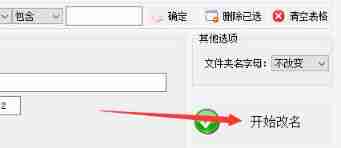
How to rename multiple folders and add unified new content to folder names
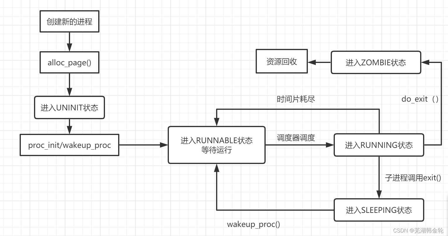
UCORE lab5 user process management experiment report
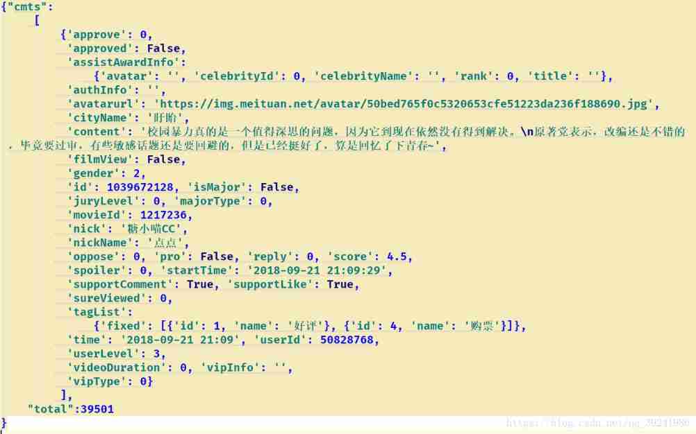
Visual analysis of data related to crawling cat's eye essays "sadness flows upstream into a river" | the most moving film of Guo Jingming's five years
What to do when programmers don't modify bugs? I teach you

The minimum number of operations to convert strings in leetcode simple problem
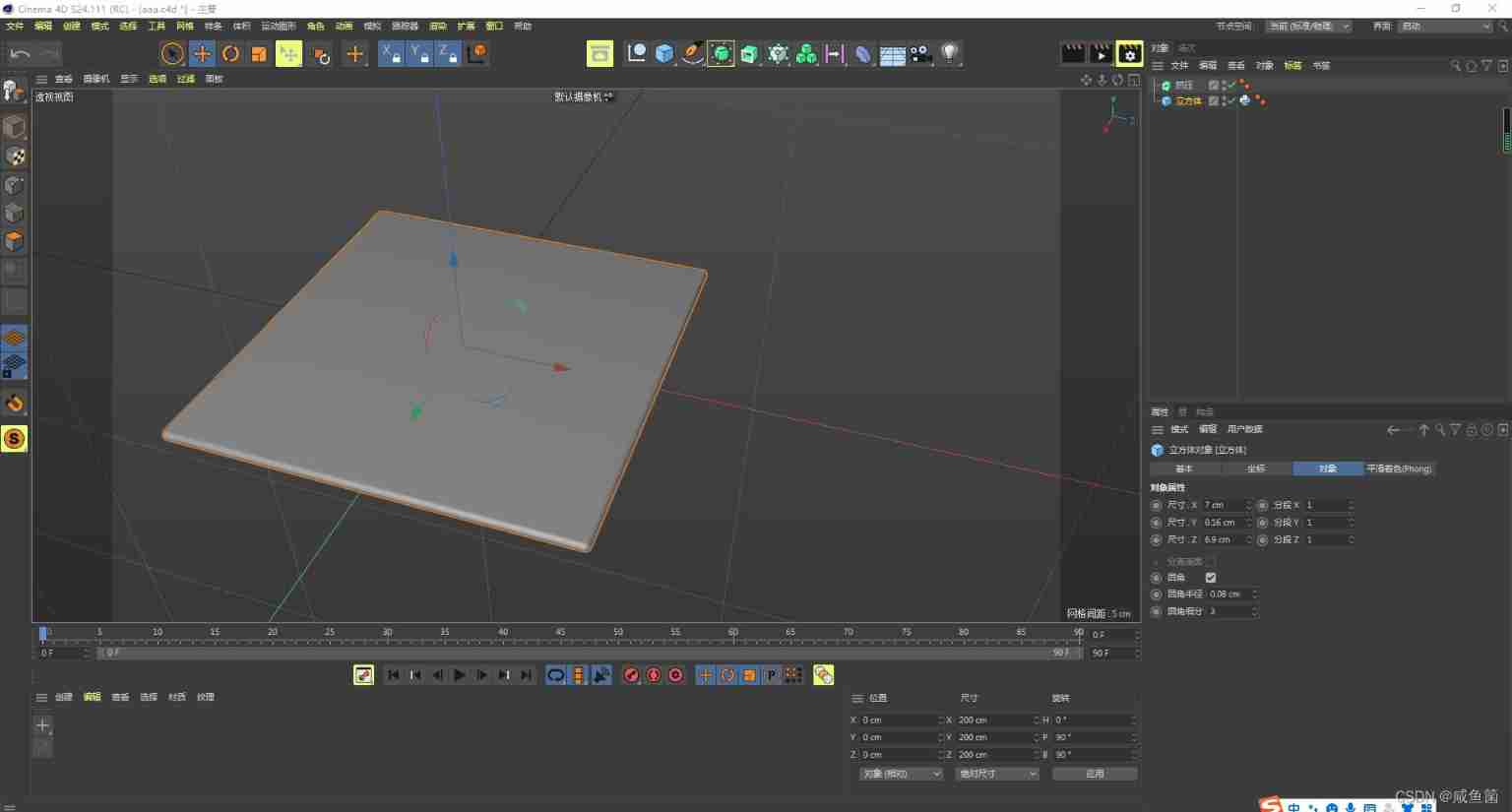
C4D quick start tutorial - Introduction to software interface
Automated testing problems you must understand, boutique summary
Réponses aux devoirs du csapp 7 8 9
What if software testing is too busy to study?


随机推荐
csapp shell lab
CSAPP家庭作業答案7 8 9章
ucore Lab 1 系统软件启动过程
MySQL数据库(一)
What are the software testing methods? Show you something different
In Oracle, start with connect by prior recursive query is used to query multi-level subordinate employees.
Réponses aux devoirs du csapp 7 8 9
Mysql database (II) DML data operation statements and basic DQL statements
How to become a good software tester? A secret that most people don't know
自动化测试中敏捷测试怎么做?
How to change XML attribute - how to change XML attribute
The wechat red envelope cover designed by the object is free! 16888
线程及线程池
Global and Chinese markets of cobalt 2022-2028: Research Report on technology, participants, trends, market size and share
UCORE LaB6 scheduler experiment report
CSAPP Shell Lab 实验报告
Global and Chinese market of portable and handheld TVs 2022-2028: Research Report on technology, participants, trends, market size and share
51 lines of code, self-made TX to MySQL software!
LeetCode#53. Maximum subarray sum
ucore lab5