当前位置:网站首页>Stc8h development (XII): I2C drive AT24C08, at24c32 series EEPROM storage
Stc8h development (XII): I2C drive AT24C08, at24c32 series EEPROM storage
2022-07-06 03:53:00 【IOsetting】
Catalog
- STC8H Development ( One ): stay Keil5 Configuration and use FwLib_STC8 Packaging Library ( Graphic, )
- STC8H Development ( Two ): stay Linux VSCode Configuration and use FwLib_STC8 Packaging Library ( Graphic, )
- STC8H Development ( 3、 ... and ): be based on FwLib_STC8 Analog to digital conversion ADC Introduce and demonstrate use case descriptions
- STC8H Development ( Four ): FwLib_STC8 Introduction of the encapsulation library and precautions for use
- STC8H Development ( 5、 ... and ): SPI drive nRF24L01 Wireless module
- STC8H Development ( 6、 ... and ): SPI drive ADXL345 Triaxial acceleration detection module
- STC8H Development ( 7、 ... and ): I2C drive MPU6050 Triaxial acceleration + Three axis angular velocity detection module
- STC8H Development ( 8、 ... and ): NRF24L01 Wireless audio transmission ( Walkie talkie prototype )
- STC8H Development ( Nine ): STC8H8K64U simulation USB HID peripherals
- STC8H Development ( Ten ): SPI drive Nokia5110 LCD(PCD8544)
- STC8H Development ( 11、 ... and ): GPIO Single line drives multiple DS18B20 Digital thermometer
- STC8H Development ( Twelve ): I2C drive AT24C08,AT24C32 series EEPROM Storage
AT24C series
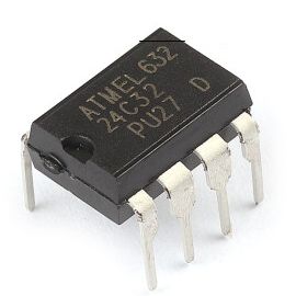
AT24C Series are common EEPROM Memory chips , It is often used to save parameters and data of power failure memory
- Capacity : The model represents its capacity , from AT24C01 To AT24C1024, Storage capacity is 1K BIT ~ 1024K BIT, Note that the unit is Bit, If converted to bytes, it is 128 byte ~ 128K byte
- voltage : The whole series has 2.7V (2.7V to 5.5V) and 1.8V (1.8V to 5.5V) Two versions , All compatible 3.3V and 5V
- encapsulation : 8-lead PDIP, 8-lead JEDEC SOIC, 8-lead MAP, 5-lead SOT23, 8-lead TSSOP and 8-ball dBGA2
Compared with other memory devices
- Small capacity
- Mr Abhisit , Almost unlimited erasure times : 10 More than ten thousand times , Typical value is millions
- Ultra long data retention : 40 In the above
- Operating temperature range : Industrial grade [-55℃,125℃]
- I2C Bus , It only needs SCL and SDA Two interfaces , And can be compared with other I2C Device reuse
- Support write protection
Because of these characteristics , AT24C It is often used in some small capacity but high stability , And the scene that needs to be rewritten repeatedly .
AT24C Device address and storage address
Device address
AT24C The device address of is a byte , In binary 1010 start , adopt A0,A1,A2 These three pin Adjustment . Depending on the capacity , There are differences between device address and addressing range
AT24C01 - AT24C16
The storage address of this series is only one byte , So memory addressing only 256 byte (2048 bit), about AT24C01, AT24C02 It's directly addressable , For larger capacity models , It is necessary to divide the memory address in combination with the device address page visit
- AT24C01, AT24C02: Device address 0xA0 - 0xAE, The first 8 Is it R/W, The same I2C Can coexist on the bus 8 Similar devices
- AT24C04: 0xA0 - 0xAC, The first 7 Is it page choice , The first 8 Is it R/W, The same I2C Can coexist on the bus 4 Similar devices
- AT24C08: 0XA0 - 0xA8, The first 6,7 Is it page choice , The first 8 Is it R/W, The same I2C Can coexist on the bus 2 Similar devices
- AT24C16: 0XA0, The first 5, 6,7 Is it page choice , The first 8 Is it R/W, The same I2C Only... Can exist on the bus 1 Similar devices
AT24C32, AT24C64
- Start with this capacity , The storage address becomes two bytes
- Device address 0xA0 - 0xAE, The first 8 Is it R/W, The same I2C Can coexist on the bus 8 Similar devices
AT24C128, AT24C256, AT24C512
- Device address 0xA0 - 0xA6, The first 5 The bit is fixed to 0, The first 8 Is it R/W, The same I2C Can coexist on the bus 4 Similar devices
- Store two bytes of address
AT24C1024
- Device address 0xA0 - 0xA4, The first 5 The bit is fixed to 0, The first 7 Is it page choice , The first 8 Is it R/W, The same I2C Can coexist on the bus 2 Similar devices
- Store two bytes of address , So memory addressing only 64K byte , 128K It needs to be divided into two page Visit
adopt STC8H visit AT24C Series memory chips
Be careful
visit AT24C when I2C The frequency of the bus should not be too high .
- AT24C Series of I2C The maximum bus frequency is 400KHz(2.7V), stay 1.8V The frequency will drop to 100KHz
- Compatible chips on the market may not meet the previous indicators
- STC8H The main frequency of the series is basically from 24MHz start , Even run directly in 36.864MHz On
- STC8H I2C The frequency of the bus is based on FOSC Calculated , In the initial debugging stage , Be sure to set a large prescaler , This can ensure that the problem does not lie in the high frequency
connection
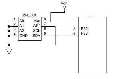
about DIP8 encapsulation , The wiring mode is the same , The test uses STC8H3K64S2, It can be directly replaced by STC8H Other models , Except for the following 4 individual pin, You also need to choose to A0, A1, A2 Pick up GND Or connect VCC
P32   -> SCL
P33   -> SDA
GND   -> GND
3.3V  -> VCC
AT24C08 Access examples
This example demonstrates the access mode of single byte storage address series models
#include "fw_hal.h"

//  Set the address  0xA0,  Corresponding A0,A1,A2 Three pin All grounded ,  Modify according to your own wiring during the test
#define AT24C_ADDR 0xA0

__CODE int8_t dat[20] = {
    0xC0,0xC1,0xC2,0xC3,0xC4,0xC5,0xC6,0xC7,0xC8,0xC9,0xCA,0xCB};

// I2C initialization
void I2C_Init(void)
{

    //  Master mode
    I2C_SetWorkMode(I2C_WorkMode_Master);
    /** * I2C  Bus frequency  = FOSC / 2 / (__prescaler__ * 2 + 4)  Set the maximum value here 0x3F */
    I2C_SetClockPrescaler(0x3F);
    //  choice I2C port
    I2C_SetPort(I2C_AlterPort_P32_P33);
    //  Enable  I2C
    I2C_SetEnabled(HAL_State_ON);
}

// GPIO initialization
void GPIO_Init(void)
{

    // SDA
    GPIO_P3_SetMode(GPIO_Pin_3, GPIO_Mode_InOut_QBD);
    // SCL
    GPIO_P3_SetMode(GPIO_Pin_2, GPIO_Mode_Output_PP);
}


int main(void)
{

    uint8_t offset, i, buf[20];

    SYS_SetClock();
    //  Turn on  UART1, baud 115200 with Timer2, 1T mode, no interrupt
    UART1_Config8bitUart(UART1_BaudSource_Timer2, HAL_State_ON, 115200);

    GPIO_Init();
    I2C_Init();
    //  Address 0x00 Write continuously 12 Bytes
    I2C_Write(AT24C_ADDR, 0x00, dat, 12);

    while(1)
    {

    	//  branch 4 Time ,  The starting address is incremented ,  Read continuously each time 6 Bytes and output through serial port
        for (offset = 0; offset < 4; offset++)
        {

            I2C_Read(AT24C_ADDR, offset, buf, 6);
            for (i = 0; i < 6; i++)
            {

                UART1_TxHex(buf[i]);
                UART1_TxChar(':');
            }
            UART1_TxString(" ");
            SYS_Delay(10);
        }
        UART1_TxString("\r\n");
        //  interval 1 second
        SYS_Delay(1000);
    }
}
Code address
- GitHub https://github.com/IOsetting/FwLib_STC8/blob/master/demo/i2c/at24c/at24c08_stc8h3k.c
- Gitee https://gitee.com/iosetting/fw-lib_-stc8/blob/master/demo/i2c/at24c/at24c08_stc8h3k.c
AT24C32 Access examples
This example demonstrates the access mode of double byte storage address series models
#include "fw_hal.h"

// AT24C device address, change according to the voltage level of A0/A1/A2
#define AT24C_ADDR 0xA0
// Test data
__CODE int8_t dat[20] = {
    0xC0,0xC1,0xC2,0xC3,0xC4,0xC5,0xC6,0xC7,0xC8,0xC9,0xCA,0xCB};

void I2C_Init(void)
{

    // Master mode
    I2C_SetWorkMode(I2C_WorkMode_Master);
    /** * I2C clock = FOSC / 2 / (__prescaler__ * 2 + 4) */
    I2C_SetClockPrescaler(0x3F);
    // Switch alternative port
    I2C_SetPort(I2C_AlterPort_P32_P33);
    // Start I2C
    I2C_SetEnabled(HAL_State_ON);
}

void GPIO_Init(void)
{

    // SDA
    GPIO_P3_SetMode(GPIO_Pin_3, GPIO_Mode_InOut_QBD);
    // SCL
    GPIO_P3_SetMode(GPIO_Pin_2, GPIO_Mode_Output_PP);
}

int main(void)
{

    uint8_t offset, i, buf[20];

    SYS_SetClock();
    // UART1 configuration: baud 115200 with Timer2, 1T mode, no interrupt
    UART1_Config8bitUart(UART1_BaudSource_Timer2, HAL_State_ON, 115200);

    GPIO_Init();
    I2C_Init();
    //  And AT24C08 The difference between the examples is that 16bit Address
    I2C_Write16BitAddr(AT24C_ADDR, 0x0000, dat, 12);

    while(1)
    {

        for (offset = 0; offset < 4; offset++)
        {

        	//  And AT24C08 The difference between the examples is that 16bit Address
            I2C_Read16BitAddr(AT24C_ADDR, 0x0000|offset, buf, 6);
            for (i = 0; i < 6; i++)
            {

                UART1_TxHex(buf[i]);
                UART1_TxChar(':');
            }
            UART1_TxString(" ");
            SYS_Delay(10);
        }
        UART1_TxString("\r\n");
        SYS_Delay(1000);
    }
}
Code address
边栏推荐
- 2.13 weekly report
- 1. New project
- 2.1 rtthread pin device details
- Schnuka: 3D vision detection application industry machine vision 3D detection
- 2.2 fonctionnement stm32 GPIO
- RT thread -- FTP of LwIP (2)
- 潘多拉 IOT 开发板学习(HAL 库)—— 实验9 PWM输出实验(学习笔记)
- [FPGA tutorial case 12] design and implementation of complex multiplier based on vivado core
- C language -- structs, unions, enumerations, and custom types
- C#(二十八)之C#鼠标事件、键盘事件
猜你喜欢
![[practice] mathematics in lottery](/img/29/2ef2b545d92451cf083ee16e09ffb4.jpg)
[practice] mathematics in lottery
mysql从一个连续时间段的表中读取缺少数据
登录mysql输入密码时报错,ERROR 1045 (28000): Access denied for user ‘root‘@‘localhost‘ (using password: NO/YES
Suggestions for new engineer team members
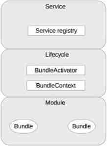
Microkernel structure understanding
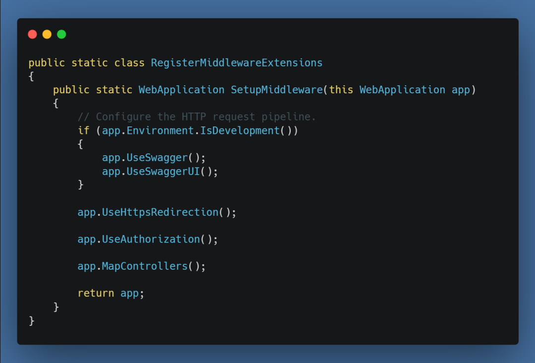
在 .NET 6 中使用 Startup.cs 更简洁的方法
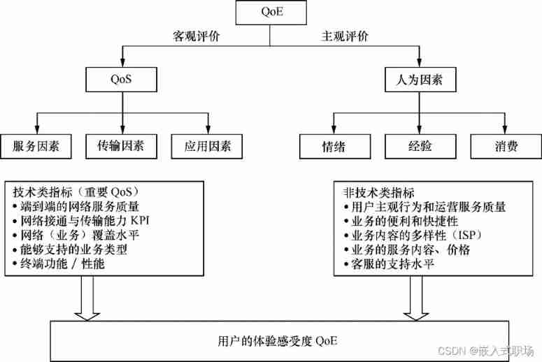
Factors affecting user perception
AcWing 243. A simple integer problem 2 (tree array interval modification interval query)
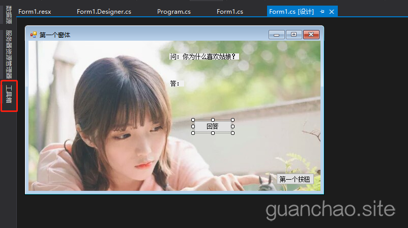
C#(二十七)之C#窗体应用
![[Key shake elimination] development of key shake elimination module based on FPGA](/img/47/c3833c077ad89d4906e425ced945bb.png)
[Key shake elimination] development of key shake elimination module based on FPGA
随机推荐
Schnuka: what is visual positioning system and how to position it
简述C语言中的符号和链接库
The ECU of 21 Audi q5l 45tfsi brushes is upgraded to master special adjustment, and the horsepower is safely and stably increased to 305 horsepower
WPF效果第一百九十一篇之框选ListBox
自动化测试怎么规范部署?
[optimization model] Monte Carlo method of optimization calculation
[prediction model] difference method model
BUAA magpie nesting
RT-Thread--Lwip之FTP(2)
mysql关于自增长增长问题
Facebook等大廠超十億用戶數據遭泄露,早該關注DID了
LTE CSFB test analysis
Mapping between QoE and KQI
Chinese brand hybrid technology: there is no best technical route, only better products
C#(三十)之C#comboBox ListView treeView
Record the process of reverse task manager
Cf464e the classic problem [shortest path, chairman tree]
[introduction to Django] 11 web page associated MySQL single field table (add, modify, delete)
Flask learning and project practice 9: WTF form verification
KS008基于SSM的新闻发布系统