当前位置:网站首页>2.1 rtthread pin device details
2.1 rtthread pin device details
2022-07-06 03:25:00 【rou252051452】
Catalog
2、PIN Initialization and registration of devices
3.1 Get the implementation of pin number
3.5 Break the binding of callback
3.6 Unbinding of interrupt callback
3.7 Enable and disable interrupts
3.8 Implementation of interrupt callback function
1、PIN Equipment description
rtthread adopt pin.c and pin.h Two files pin Equipment management . adopt pin.h Structural body in rt_device_pin Conduct pin Definition of equipment ,pin The device inherits from the device base class rt_device,rt_device Inherited from rt_object Base class , The inheritance relationship is as follows

PIN The device realizes the definition of rt_device Inheritance of device base class , Members of the structure rt_pin_ops To achieve pin The specific operation of the equipment .
struct rt_device_pin
{
    struct rt_device parent;
    const struct rt_pin_ops *ops;
};
struct rt_pin_ops
{
void (*pin_mode)(struct rt_device *device, rt_base_t pin, rt_base_t mode);
void (*pin_write)(struct rt_device *device, rt_base_t pin, rt_base_t value);
int (*pin_read)(struct rt_device *device, rt_base_t pin);
rt_err_t (*pin_attach_irq)(struct rt_device *device, rt_int32_t pin,
rt_uint32_t mode, void (*hdr)(void *args), void *args);
rt_err_t (*pin_detach_irq)(struct rt_device *device, rt_int32_t pin);
rt_err_t (*pin_irq_enable)(struct rt_device *device, rt_base_t pin, rt_uint32_t enabled);
rt_base_t (*pin_get)(const char *name);
};2、PIN Initialization and registration of devices
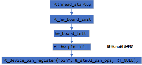
Start-up phase rtthread It will be based on whether RT_USING_PIN Definition , stay hw_board_init In function pin Initialization of the device , stay rt_hw-pin_init The function initializes the clock first , Finally call the function rt_device_pin_register To achieve STM32 Of IO and pin Device association and device mounting .
/*
 Conduct PIN Definition of equipment structure
*/
static struct rt_device_pin _hw_pin;

int rt_device_pin_register(const char *name, const struct rt_pin_ops *ops, void *user_data)
{
    /*
        PIN The parent device of the device , Define the type of the device base class , Defined as RT_Device_Class_Miscellaneous, Miscellaneous
    */
    _hw_pin.parent.type         = RT_Device_Class_Miscellaneous;

    /*
         The send receive callback function is empty
    */
    _hw_pin.parent.rx_indicate  = RT_NULL;
    _hw_pin.parent.tx_complete  = RT_NULL;

    /*
         The initialization light of the device base class is related to the function pointer assignment .
    */
#ifdef RT_USING_DEVICE_OPS
    _hw_pin.parent.ops          = &pin_ops;
#else
    _hw_pin.parent.init         = RT_NULL;
    _hw_pin.parent.open         = RT_NULL;
    _hw_pin.parent.close        = RT_NULL;
    _hw_pin.parent.read         = _pin_read;
    _hw_pin.parent.write        = _pin_write;
    _hw_pin.parent.control      = _pin_control;
#endif

    /*
        PIN equipment ops, namely STM32 The specific implementation of the assignment .
    */
    _hw_pin.ops                 = ops;
    _hw_pin.parent.user_data    = user_data;


    /*
         Device registration
    */
    /* register a character device */
    rt_device_register(&_hw_pin.parent, name, RT_DEVICE_FLAG_RDWR);

    return 0;
}
rt_device_pin_register("pin", &_stm32_pin_ops, RT_NULL) In the parameter _stm32_pin_ops by rt_pin_ops, The specific definitions are as follows , Realized GPIO Mode configuration , I / O control , Functions such as interrupt control and pin search are in STM32 Get the definition of function pointer in the specific implementation mode .
const static struct rt_pin_ops _stm32_pin_ops =
{
    stm32_pin_mode,
    stm32_pin_write,
    stm32_pin_read,
    stm32_pin_attach_irq,
    stm32_pin_dettach_irq,
    stm32_pin_irq_enable,
    stm32_pin_get,
};
3、PIN Operation of equipment
PIN The device provides the following interface functions
| function | describe |
|---|---|
| rt_pin_get() | Get pin number |
| rt_pin_mode() | Set pin mode |
| rt_pin_write() | Set pin level |
| rt_pin_read() | Read pin level |
| rt_pin_attach_irq() | Binding pin interrupt callback function |
| rt_pin_irq_enable() | Enable pin interrupt |
| rt_pin_detach_irq() | Off pin interrupt callback function |
3.1 Get the implementation of pin number
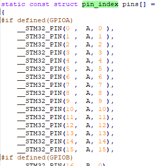
RT-Thread The pin number provided should be distinguished from the pin number of the chip , They are not the same concept , The pin number is determined by PIN Device driver definition , Related to specific chips . Pin serial number is an important parameter for the subsequent implementation of other input and output interrupt functions .STM32 The drive of is right GPIOA(0-15) To GPIOx(0-15) The numbering operation is carried out in sequence .
RTT The official document description is for STM32 Of GPIO drive drv_gpio.c There are three ways to implement pin numbering :
3.1.1 Use API
Notice here
The old version of drv_gpio.c The file in _stm32_pin_ops There is no function defined in stm32_pin_get, The implementation of the , So the old version of the driver cannot be used API Get pin number . New construction , The driver used by the system is any old version
gpio The driver needs to be updated , It can be downloaded from gitee Download the file bsp/stm32/libraries/HAL_Drivers/drv_gpio.c · RT-Thread/rt-thread - Gitee.com. The specific implementation function is as follows
/*
     According to the port number of the input string A-Z, Convert to numeric 0-25
     According to the pin number of the input string 0-15, Convert to numeric 0-15
     Combine the two. The port number is high , Pin number is status
*/
static rt_base_t stm32_pin_get(const char *name)
{
    rt_base_t pin = 0;
    int hw_port_num, hw_pin_num = 0;
    int i, name_len;

    name_len = rt_strlen(name);

    if ((name_len < 4) || (name_len >= 6))          // Perform string length verification PA.0   PA.15   The shortest 4, The longest 5
    {
        return -RT_EINVAL;
    }
    if ((name[0] != 'P') || (name[2] != '.'))      // The first string must be P    The third must be .
    {
        return -RT_EINVAL;
    }

    if ((name[1] >= 'A') && (name[1] <= 'Z'))      // The port range is A-Z
    {
        hw_port_num = (int)(name[1] - 'A');        // Port number calculation ,A-Z Convert to 0-25
    }
    else
    {
        return -RT_EINVAL;
    }

    for (i = 3; i < name_len; i++)                // According to the... Of the string 4 Number conversion PA.0=0  PA.15 = 15
    {
        hw_pin_num *= 10;
        hw_pin_num += name[i] - '0';
    }

    pin = PIN_NUM(hw_port_num, hw_pin_num);        // Process the last pin number

    return pin;
}
Finally, call the macro definition as follows to obtain the pin number
#define PIN_NUM(port, no) (((((port) & 0xFu) << 4) | ((no) & 0xFu)))The calculation results are shown in the following table , follow-up IO And so on
| name | port | no | result | name | port | no | result |
| PA.0 | 0 | 0 | 0 | PB.0 | 1 | 0 | 16 |
| PA.1 | 0 | 1 | 1 | PB.1 | 1 | 1 | 17 |
| PA.2 | 0 | 2 | 2 | PB.2 | 1 | 2 | 18 |
| PA.3 | 0 | 3 | 3 | PB.3 | 1 | 3 | 19 |
| PA.4 | 0 | 4 | 4 | PB.4 | 1 | 4 | 20 |
| PA.5 | 0 | 5 | 5 | PB.5 | 1 | 5 | 21 |
| PA.6 | 0 | 6 | 6 | PB.6 | 1 | 6 | 22 |
| PA.7 | 0 | 7 | 7 | PB.7 | 1 | 7 | 23 |
| PA.8 | 0 | 8 | 8 | PB.8 | 1 | 8 | 24 |
| PA.9 | 0 | 9 | 9 | PB.9 | 1 | 9 | 25 |
| PA.10 | 0 | 10 | 10 | PB.10 | 1 | 10 | 26 |
| PA.11 | 0 | 11 | 11 | PB.11 | 1 | 11 | 27 |
| PA.12 | 0 | 12 | 12 | PB.12 | 1 | 12 | 28 |
| PA.13 | 0 | 13 | 13 | PB.13 | 1 | 13 | 29 |
| PA.14 | 0 | 14 | 14 | PB.14 | 1 | 14 | 30 |
| PA.15 | 0 | 15 | 15 | PB.15 | 1 | 15 | 31 |
3.1.2 Use a macro to define
in the light of STM32,RTT Provides macro definitions GET_PIN To get the pin number , No more updates drv_gpio Before driving , This definition again drv_common.h Is defined in , After updating the driver drv_gpio.h It is also defined in , The two definitions are the same . The contents are as follows .
//drv_common.h Macro definition in
#define __STM32_PORT(port)  GPIO##port##_BASE
#define GET_PIN(PORTx,PIN) (rt_base_t)((16 * ( ((rt_base_t)__STM32_PORT(PORTx) - (rt_base_t)GPIOA_BASE)/(0x0400UL) )) + PIN)

//drv_gpio.h Macro definition in
#define __STM32_PORT(port)  GPIO##port##_BASE

#if defined(SOC_SERIES_STM32MP1)
#define GET_PIN(PORTx,PIN) (GPIO##PORTx == GPIOZ) ? (176 + PIN) : ((rt_base_t)((16 * ( ((rt_base_t)__STM32_PORT(PORTx) - (rt_base_t)GPIOA_BASE)/(0x1000UL) )) + PIN))
#else
#define GET_PIN(PORTx,PIN) (rt_base_t)((16 * ( ((rt_base_t)__STM32_PORT(PORTx) - (rt_base_t)GPIOA_BASE)/(0x0400UL) )) + PIN)
#endif
Pictured above , Yes GET_PIN The macro definition is repeatedly defined , It can be seen that drv_gpio.h Macro definitions are precompiled in , Contains STM32MP1 Support for .
Global search GET_PIN The usage of is as follows
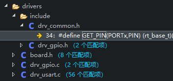
board.h、drv_gpio.h and drv_usart.c Have been carried out drv_common.h The inclusion of . Only in drv_gpio.c In the document drv_gpio.h The inclusion of . So we can put drv_gpio.h About China GET_PIN Delete the relevant macro definitions of ( Don't involve STM32MP1 Use ). To ensure the uniqueness of macro definitions .
Macro definitions are based on parameters portx Obtain the address of the pin port , take A-Z Convert to 0-25. Parameters PIN For the specific port IO. The final conversion result is port serial number *16+IO Number . And API The conversion result is the same .
| Macro definition | PORTx | 16 * ( ((rt_base_t)__STM32_PORT(PORTx) - (rt_base_t)GPIOA_BASE)/(0x0400UL) ) | PIN | result | |
| GET_PIN(A, 0) | GPIOA_BASE | D3_AHB1PERIPH_BASE + 0x0000UL | 0 | 0 | 0 |
| GET_PIN(A, 1) | GPIOA_BASE | D3_AHB1PERIPH_BASE + 0x0000UL | 0 | 0 | 0 |
| GET_PIN(A, 2) | GPIOA_BASE | D3_AHB1PERIPH_BASE + 0x0000UL | 0 | 0 | 0 |
| GET_PIN(A, 3) | GPIOA_BASE | D3_AHB1PERIPH_BASE + 0x0000UL | 0 | 0 | 0 |
| GET_PIN(B, 0) | GPIOB_BASE | D3_AHB1PERIPH_BASE + 0x0400UL | 1 | 0 | 16 |
| GET_PIN(B, 1) | GPIOB_BASE | D3_AHB1PERIPH_BASE + 0x0400UL | 1 | 1 | 17 |
| GET_PIN(B, 2) | GPIOB_BASE | D3_AHB1PERIPH_BASE + 0x0400UL | 1 | 2 | 18 |
3.1.3 View driver file
The old version of drv_gpio The driver provides the corresponding definition of pin and number , You can define the pin serial number directly by viewing .
The new version of driver updates the pin number recognition logic , No longer provide the way to view the driver file .
3.2 Set pin mode
rtt adopt rt_pin_mode Configure pin mode
void rt_pin_mode(rt_base_t pin, rt_base_t mode)
{
    RT_ASSERT(_hw_pin.ops != RT_NULL);
    _hw_pin.ops->pin_mode(&_hw_pin.parent, pin, mode);
}
The function finally called is pin Equipment ops Under the pin_mode function , In the initial stage, the function pointer is set to stm32_pin_mode, The specific implementation is as follows
/*
    1、 Identification of pin serial number
         Define by macro
        #define PIN_STPIN(pin) ((uint16_t)(1u << PIN_NO(pin)))     Convert to bit information
        #define PIN_NO(pin) ((uint8_t)((pin) & 0xFu))              Convert to 0-15
         To identify serial numbers
    2、 Port identification
        #define PIN_STPORT(pin) ((GPIO_TypeDef *)(GPIOA_BASE + (0x400u * PIN_PORT(pin))))
         To convert the pin number to the address of the port structure .
    3、 Finally, call the library function to GPIO Configuration of .
*/
static void stm32_pin_mode(rt_device_t dev, rt_base_t pin, rt_base_t mode)
{
    GPIO_InitTypeDef GPIO_InitStruct;

    // Verify that the port is larger than the maximum port , Is it legal
    if (PIN_PORT(pin) >= PIN_STPORT_MAX)
    {
        return;
    }

    // configure port IO It is the default push-pull output , No up and down , Output speed HIGH
    GPIO_InitStruct.Pin = PIN_STPIN(pin);
    GPIO_InitStruct.Mode = GPIO_MODE_OUTPUT_PP;
    GPIO_InitStruct.Pull = GPIO_NOPULL;
    GPIO_InitStruct.Speed = GPIO_SPEED_FREQ_HIGH;

    // Configure according to the mode of the actual input parameters
    if (mode == PIN_MODE_OUTPUT)
    {
        /* output setting */
        GPIO_InitStruct.Mode = GPIO_MODE_OUTPUT_PP;
        GPIO_InitStruct.Pull = GPIO_NOPULL;
    }
    else if (mode == PIN_MODE_INPUT)
    {
        /* input setting: not pull. */
        GPIO_InitStruct.Mode = GPIO_MODE_INPUT;
        GPIO_InitStruct.Pull = GPIO_NOPULL;
    }
    else if (mode == PIN_MODE_INPUT_PULLUP)
    {
        /* input setting: pull up. */
        GPIO_InitStruct.Mode = GPIO_MODE_INPUT;
        GPIO_InitStruct.Pull = GPIO_PULLUP;
    }
    else if (mode == PIN_MODE_INPUT_PULLDOWN)
    {
        /* input setting: pull down. */
        GPIO_InitStruct.Mode = GPIO_MODE_INPUT;
        GPIO_InitStruct.Pull = GPIO_PULLDOWN;
    }
    else if (mode == PIN_MODE_OUTPUT_OD)
    {
        /* output setting: od. */
        GPIO_InitStruct.Mode = GPIO_MODE_OUTPUT_OD;
        GPIO_InitStruct.Pull = GPIO_NOPULL;
    }
    // Call the library function to initialize
    HAL_GPIO_Init(PIN_STPORT(pin), &GPIO_InitStruct);
}
3.3 Output control
rtt adopt rt_pin_write Configure pin mode .
void rt_pin_write(rt_base_t pin, rt_base_t value)
{
    RT_ASSERT(_hw_pin.ops != RT_NULL);
    _hw_pin.ops->pin_write(&_hw_pin.parent, pin, value);
}
The function finally called is pin Equipment ops Under the pin_write function , In the initial stage, the function pointer is set to stm32_pin_write, The specific implementation is as follows
/*
    1、 Identification of pin serial number
         Define by macro
        #define PIN_STPIN(pin) ((uint16_t)(1u << PIN_NO(pin)))     Convert to bit information
        #define PIN_NO(pin) ((uint8_t)((pin) & 0xFu))              Convert to 0-15
         To identify serial numbers
    2、 Port identification
        #define PIN_STPORT(pin) ((GPIO_TypeDef *)(GPIOA_BASE + (0x400u * PIN_PORT(pin))))
         To convert the pin number to the address of the port structure .
    3、 Finally, call the library function to GPIO Configuration of .
*/
static void stm32_pin_write(rt_device_t dev, rt_base_t pin, rt_base_t value)
{
    GPIO_TypeDef *gpio_port;
    uint16_t gpio_pin;

    if (PIN_PORT(pin) < PIN_STPORT_MAX)
    {
        // Get port
        gpio_port = PIN_STPORT(pin);
        // obtain IO Number
        gpio_pin = PIN_STPIN(pin);
        // Library function output
        HAL_GPIO_WritePin(gpio_port, gpio_pin, (GPIO_PinState)value);
    }
}
3.4 Input to get
rtt adopt rt_pin_read Configure pin mode .
int rt_pin_read(rt_base_t pin)
{
    RT_ASSERT(_hw_pin.ops != RT_NULL);
    return _hw_pin.ops->pin_read(&_hw_pin.parent, pin);
}
The function finally called is pin Equipment ops Under the pin_read function , In the initial stage, the function pointer is set to stm32_pin_read, The specific implementation is as follows
/*
    1、 Identification of pin serial number
         Define by macro
        #define PIN_STPIN(pin) ((uint16_t)(1u << PIN_NO(pin)))     Convert to bit information
        #define PIN_NO(pin) ((uint8_t)((pin) & 0xFu))              Convert to 0-15
         To identify serial numbers
    2、 Port identification
        #define PIN_STPORT(pin) ((GPIO_TypeDef *)(GPIOA_BASE + (0x400u * PIN_PORT(pin))))
         To convert the pin number to the address of the port structure .
    3、 Finally, call the library function to GPIO Configuration of .
*/
static int stm32_pin_read(rt_device_t dev, rt_base_t pin)
{
    GPIO_TypeDef *gpio_port;
    uint16_t gpio_pin;
    int value = PIN_LOW;

    if (PIN_PORT(pin) < PIN_STPORT_MAX)
    {
        gpio_port = PIN_STPORT(pin);
        gpio_pin = PIN_STPIN(pin);
        value = HAL_GPIO_ReadPin(gpio_port, gpio_pin);
    }
    return value;
}
3.5 Break the binding of callback
rtt adopt rt_pin_attach_irq Bind interrupt callback .
rt_err_t rt_pin_attach_irq(rt_int32_t pin, rt_uint32_t mode,void (*hdr)(void *args), void  *args)
{
    RT_ASSERT(_hw_pin.ops != RT_NULL);
    if(_hw_pin.ops->pin_attach_irq)
    {
        return _hw_pin.ops->pin_attach_irq(&_hw_pin.parent, pin, mode, hdr, args);
    }
    return -RT_ENOSYS;
}
The function finally called is pin Equipment ops Under the pin_attach_irq function , In the initial stage, the function pointer is set to stm32_pin_attach_irq, The specific implementation is as follows
/*
     This function does not perform the underlying STM32 The actual operation of external interrupts .
     the pin Assignment of interrupt related structure of the device .
*/
static rt_err_t stm32_pin_attach_irq(struct rt_device *device, rt_int32_t pin, rt_uint32_t mode, void (*hdr)(void *args), void *args)
{
    rt_base_t level;
    rt_int32_t irqindex = -1;

    // Identify whether the port number is correct
    if (PIN_PORT(pin) >= PIN_STPORT_MAX)
    {
        return -RT_ENOSYS;
    }
    /*
         Identify the interrupt sequence number
        1、 The interrupt sequence number is identified through the pin sequence number , First, through PIN_STDPIN Bit conversion
        2、 By function bit2bitno It realizes the recognition of bit number .
        3、 Actually, it can be achieved through PIN_NO To replace the above process for identification
    */
    irqindex = bit2bitno(PIN_STPIN(pin));
    /*
         Judge whether the interrupt sequence number is legal
    */
    if (irqindex < 0 || irqindex >= ITEM_NUM(pin_irq_map))
    {
        return RT_ENOSYS;
    }
    /*
         Conduct pin The interrupt mode of the device and the assignment of the callback function
    */
    level = rt_hw_interrupt_disable();
    if (pin_irq_hdr_tab[irqindex].pin == pin &&
        pin_irq_hdr_tab[irqindex].hdr == hdr &&
        pin_irq_hdr_tab[irqindex].mode == mode &&
        pin_irq_hdr_tab[irqindex].args == args)
    {
        rt_hw_interrupt_enable(level);
        return RT_EOK;
    }
    if (pin_irq_hdr_tab[irqindex].pin != -1)
    {
        rt_hw_interrupt_enable(level);
        return RT_EBUSY;
    }
    pin_irq_hdr_tab[irqindex].pin = pin;
    pin_irq_hdr_tab[irqindex].hdr = hdr;
    pin_irq_hdr_tab[irqindex].mode = mode;
    pin_irq_hdr_tab[irqindex].args = args;
    rt_hw_interrupt_enable(level);

    return RT_EOK;
}
3.6 Unbinding of interrupt callback
rtt adopt rt_pin_detach_irq Configure pin mode .
rt_err_t rt_pin_detach_irq(rt_int32_t pin)
{
    RT_ASSERT(_hw_pin.ops != RT_NULL);
    if(_hw_pin.ops->pin_detach_irq)
    {
        return _hw_pin.ops->pin_detach_irq(&_hw_pin.parent, pin);
    }
    return -RT_ENOSYS;
}
The function finally called is pin Equipment ops Under the pin_detach_irq function , In the initial stage, the function pointer is set to stm32_pin_dettach_irq, The specific implementation is as follows
static rt_err_t stm32_pin_dettach_irq(struct rt_device *device, rt_int32_t pin)
{
    rt_base_t level;
    rt_int32_t irqindex = -1;

    // Identify whether the input port is legal
    if (PIN_PORT(pin) >= PIN_STPORT_MAX)
    {
        return -RT_ENOSYS;
    }
    /*
         Identify the interrupt sequence number
        1、 The interrupt sequence number is identified through the pin sequence number , First, through PIN_STDPIN Bit conversion
        2、 By function bit2bitno It realizes the recognition of bit number .
        3、 Actually, it can be achieved through PIN_NO To replace the above process for identification
    */
    irqindex = bit2bitno(PIN_STPIN(pin));
    /*
         Judge whether the interrupt sequence number is legal
    */
    if (irqindex < 0 || irqindex >= ITEM_NUM(pin_irq_map))
    {
        return RT_ENOSYS;
    }
    /*
         Reset of interrupt mode and interrupt pin callback function
    */
    level = rt_hw_interrupt_disable();
    if (pin_irq_hdr_tab[irqindex].pin == -1)
    {
        rt_hw_interrupt_enable(level);
        return RT_EOK;
    }
    pin_irq_hdr_tab[irqindex].pin = -1;
    pin_irq_hdr_tab[irqindex].hdr = RT_NULL;
    pin_irq_hdr_tab[irqindex].mode = 0;
    pin_irq_hdr_tab[irqindex].args = RT_NULL;
    rt_hw_interrupt_enable(level);

    return RT_EOK;
}
3.7 Enable and disable interrupts
rtt adopt rt_pin_irq_enable Configure pin mode .
rt_err_t rt_pin_irq_enable(rt_base_t pin, rt_uint32_t enabled)
{
    RT_ASSERT(_hw_pin.ops != RT_NULL);
    if(_hw_pin.ops->pin_irq_enable)
    {
        return _hw_pin.ops->pin_irq_enable(&_hw_pin.parent, pin, enabled);
    }
    return -RT_ENOSYS;
}
The function finally called is pin Equipment ops Under the pin_irq_enable function , In the initial stage, the function pointer is set to stm32_pin_irq_enable, The specific implementation is as follows
static rt_err_t stm32_pin_irq_enable(struct rt_device *device, rt_base_t pin,rt_uint32_t enabled)
{
    const struct pin_irq_map *irqmap;
    rt_base_t level;
    rt_int32_t irqindex = -1;
    GPIO_InitTypeDef GPIO_InitStruct;

    // distinguish IO Is it legal
    if (PIN_PORT(pin) >= PIN_STPORT_MAX)
    {
        return -RT_ENOSYS;
    }
    // To interrupt
    if (enabled == PIN_IRQ_ENABLE)
    {
        // Get and judge whether the interrupt sequence number is legal
        irqindex = bit2bitno(PIN_STPIN(pin));
        if (irqindex < 0 || irqindex >= ITEM_NUM(pin_irq_map))
        {
            return RT_ENOSYS;
        }

        level = rt_hw_interrupt_disable();

        if (pin_irq_hdr_tab[irqindex].pin == -1)
        {
            rt_hw_interrupt_enable(level);
            return RT_ENOSYS;
        }

        // Look up the table to get the content corresponding to the interrupt number
        irqmap = &pin_irq_map[irqindex];

        /* Interrupt specific configuration */
        GPIO_InitStruct.Pin = PIN_STPIN(pin);
        GPIO_InitStruct.Speed = GPIO_SPEED_FREQ_HIGH;
        switch (pin_irq_hdr_tab[irqindex].mode)
        {
        case PIN_IRQ_MODE_RISING:
            GPIO_InitStruct.Pull = GPIO_PULLDOWN;
            GPIO_InitStruct.Mode = GPIO_MODE_IT_RISING;
            break;
        case PIN_IRQ_MODE_FALLING:
            GPIO_InitStruct.Pull = GPIO_PULLUP;
            GPIO_InitStruct.Mode = GPIO_MODE_IT_FALLING;
            break;
        case PIN_IRQ_MODE_RISING_FALLING:
            GPIO_InitStruct.Pull = GPIO_NOPULL;
            GPIO_InitStruct.Mode = GPIO_MODE_IT_RISING_FALLING;
            break;
        }
        HAL_GPIO_Init(PIN_STPORT(pin), &GPIO_InitStruct);
        // Set interrupt priority
        HAL_NVIC_SetPriority(irqmap->irqno, 5, 0);
        HAL_NVIC_EnableIRQ(irqmap->irqno);
        pin_irq_enable_mask |= irqmap->pinbit;

        rt_hw_interrupt_enable(level);
    }

    // Disable interrupt
    else if (enabled == PIN_IRQ_DISABLE)
    {
        irqmap = get_pin_irq_map(PIN_STPIN(pin));
        if (irqmap == RT_NULL)
        {
            return RT_ENOSYS;
        }

        level = rt_hw_interrupt_disable();
        // Reset pins
        HAL_GPIO_DeInit(PIN_STPORT(pin), PIN_STPIN(pin));

        pin_irq_enable_mask &= ~irqmap->pinbit;
#if defined(SOC_SERIES_STM32F0) || defined(SOC_SERIES_STM32G0)
        if ((irqmap->pinbit >= GPIO_PIN_0) && (irqmap->pinbit <= GPIO_PIN_1))
        {
            if (!(pin_irq_enable_mask & (GPIO_PIN_0 | GPIO_PIN_1)))
            {
                HAL_NVIC_DisableIRQ(irqmap->irqno);
            }
        }
        else if ((irqmap->pinbit >= GPIO_PIN_2) && (irqmap->pinbit <= GPIO_PIN_3))
        {
            if (!(pin_irq_enable_mask & (GPIO_PIN_2 | GPIO_PIN_3)))
            {
                HAL_NVIC_DisableIRQ(irqmap->irqno);
            }
        }
        else if ((irqmap->pinbit >= GPIO_PIN_4) && (irqmap->pinbit <= GPIO_PIN_15))
        {
            if (!(pin_irq_enable_mask & (GPIO_PIN_4 | GPIO_PIN_5 | GPIO_PIN_6 | GPIO_PIN_7 | GPIO_PIN_8 | GPIO_PIN_9 |
                                         GPIO_PIN_10 | GPIO_PIN_11 | GPIO_PIN_12 | GPIO_PIN_13 | GPIO_PIN_14 | GPIO_PIN_15)))
            {
                HAL_NVIC_DisableIRQ(irqmap->irqno);
            }
        }
        else
        {
            HAL_NVIC_DisableIRQ(irqmap->irqno);
        }
#else
        if ((irqmap->pinbit >= GPIO_PIN_5) && (irqmap->pinbit <= GPIO_PIN_9))
        {
            if (!(pin_irq_enable_mask & (GPIO_PIN_5 | GPIO_PIN_6 | GPIO_PIN_7 | GPIO_PIN_8 | GPIO_PIN_9)))
            {
                HAL_NVIC_DisableIRQ(irqmap->irqno);
            }
        }
        else if ((irqmap->pinbit >= GPIO_PIN_10) && (irqmap->pinbit <= GPIO_PIN_15))
        {
            if (!(pin_irq_enable_mask & (GPIO_PIN_10 | GPIO_PIN_11 | GPIO_PIN_12 | GPIO_PIN_13 | GPIO_PIN_14 | GPIO_PIN_15)))
            {
                HAL_NVIC_DisableIRQ(irqmap->irqno);
            }
        }
        else
        {
            HAL_NVIC_DisableIRQ(irqmap->irqno);
        }
#endif
        rt_hw_interrupt_enable(level);
    }
    else
    {
        return -RT_ENOSYS;
    }

    return RT_EOK;
}
3.8 Implementation of interrupt callback function
After enabling the external interrupt ,STM32 After the interrupt is triggered, the bottom layer of the will call the interrupt function as follows .
- EXTI0_IRQHandler~EXTI4_IRQHandler
- EXTI9_5_IRQHandler
- EXTI15_10_IRQHandler
The internal call of the function is HAL_GPIO_EXTI_IRQHandler. The callback function is finally called inside this function HAL_GPIO_EXTI_Callback To implement the callback function .
void HAL_GPIO_EXTI_Callback(uint16_t GPIO_Pin)
{
    pin_irq_hdr(bit2bitno(GPIO_Pin));
}
The callback function above called pin_irq_hdr It was carried out with pin The association of the callback function bound by the device .
rt_inline void pin_irq_hdr(int irqno)
{
    if (pin_irq_hdr_tab[irqno].hdr)
    {
        pin_irq_hdr_tab[irqno].hdr(pin_irq_hdr_tab[irqno].args);
    }
}边栏推荐
- Performance test method of bank core business system
- 数据分析——seaborn可视化(笔记自用)
- NR modulation 1
- Leetcode problem solving -- 99 Restore binary search tree
- Teach you to build your own simple BP neural network with pytoch (take iris data set as an example)
- 【SLAM】ORB-SLAM3解析——跟踪Track()(3)
- Restful style
- The real machine cannot access the shooting range of the virtual machine, and the real machine cannot Ping the virtual machine
- Jenkins basic knowledge ----- detailed explanation of 03pipeline code
- 教你用Pytorch搭建一个自己的简单的BP神经网络( 以iris数据集为例 )
猜你喜欢

Canvas cut blocks game code
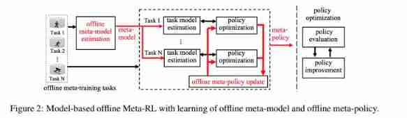
ASU & OSU | model based regularized off-line meta reinforcement learning
2、GPIO相关操作

蓝色样式商城网站页脚代码

深入刨析的指针(题解)
EDCircles: A real-time circle detector with a false detection control 翻译

Python implementation of maddpg - (1) openai maddpg environment configuration
遥感图像超分辨率论文推荐
MPLS experiment
![Buuctf question brushing notes - [geek challenge 2019] easysql 1](/img/37/c38a933ce7fa5d2b8fa597965ffcb2.png)
Buuctf question brushing notes - [geek challenge 2019] easysql 1
随机推荐
教你用Pytorch搭建一个自己的简单的BP神经网络( 以iris数据集为例 )
Teach you to build your own simple BP neural network with pytoch (take iris data set as an example)
Mysqldump data backup
Computer graduation project asp Net fitness management system VS development SQLSERVER database web structure c programming computer web page source code project
NR modulation 1
1、工程新建
[slam] lidar camera external parameter calibration (Hong Kong University marslab) does not need a QR code calibration board
Pytorch基础——(2)张量(tensor)的数学运算
手写数据库客户端
js凡客banner轮播图js特效
指针笔试题~走近大厂
施努卡:什么是视觉定位系统 视觉系统如何定位
遥感图像超分辨率论文推荐
[padding] an error is reported in the prediction after loading the model weight attributeerror: 'model' object has no attribute '_ place‘
下一个行业风口:NFT 数字藏品,是机遇还是泡沫?
11. Container with the most water
SAP ALV color code corresponding color (finishing)
Explore pointers and pointer types in depth
OCR文字識別方法綜述
Linear programming matlab