当前位置:网站首页>Assembly and Interface Technology Experiment 6 - ADDA conversion experiment, AD acquisition system in interrupt mode
Assembly and Interface Technology Experiment 6 - ADDA conversion experiment, AD acquisition system in interrupt mode
2022-07-06 22:11:00 【dor. yang】
One 、 The experiment purpose
The experiment used 8259A,ADC0809, Digital tube to complete the design of a data acquisition system , The purpose is to understand the interrupt mode A/D Implementation method of data collection , Master the hardware design and the writing method of interrupt program , It is the training of students' comprehensive experimental ability .
Two 、 Experimental content
Use ADC0809 The passage of 0, Access 0-5V DC voltage of , use “ DC signal ” The potentiometer adjusts the analog voltage value ,A/D End of conversion signal EOC Connected to the main 8259A Of MIR3 On , collection 100 Data and store it in memory , At the same time, the collected 16 Hexadecimal data is displayed on the nixie tube . Please adjust it many times 0-5V The voltage value of ( Whirl “ DC signal ” knob ), Conduct A/D collection , And observe the changes of data in memory .
3、 ... and 、 Experimental phenomena
Every time I collect 100 Data may be the same ( The data of the nixie tube may also remain unchanged ), When “ DC signal ” Different data can be collected when the knob is rotated .
Four 、 Experimental wiring diagram
5、 ... and 、 The experimental steps
1、 Connect the experimental circuit correctly according to the schematic diagram ( Need to connect the red line ).
The circuit diagram is as follows :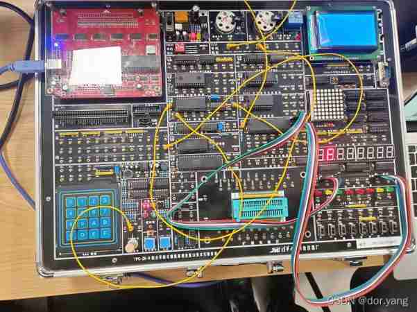
2、 Correctly understand the experimental principle .
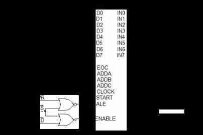
take 298H As a result of A/D0809 The port of , take 280H As a result of 8255A The port of .
take A/D0809 At the end of data conversion EOC High level of as 8259A The interrupt source of , Connected to MIRQ3, Of the main film IR3. in addition 8255A Of A Mouth in 0 Output segment code in mode ,B Mouth in 0 Output bit code in mode , Make the nixie tube display .
The flow chart of the main program is as follows :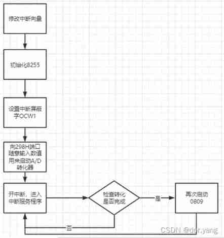
Flow chart of interrupt service program :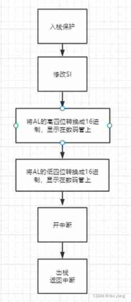
3、 Write the experimental program , And debugging on the computer , Observe the results of the experiment .
The experimental procedure is as follows :
STACKS   SEGMENT
STA       DW 512 DUP(?)
TOP       EQU  LENGTH STA
STACKS     ENDS

DATA        SEGMENT
IO0809A     EQU       298H
LED         DB        3FH,06H,5BH,4FH,66H,6DH,7DH,07H,7FH,6FH,77H,7CH,39H,5EH,79H,71H
TMP_1        DB    ?
TMP_2        DB    ?
TMP          DB    ?
DATA        ENDS

CODE         SEGMENT
ASSUME CS:CODE,DS:DATA,SS:STACKS
START:
    MOV AX,CS
    MOV DS,AX
    MOV DX,OFFSET INT3      ; System function call 、 Set interrupt vector 、 from DS:DX Point to four byte address


    MOV AX,250BH         ; AL= Interrupt type number (=0BH---0B*4= Vector table address )
    INT 21H                ; ( Realize adding INT3 The address of )

    MOV DX,283H     ;8255 Command port address , To initialize
    MOV AL,10001001B ; Set the way it works ,A Working in 0 Mode input ,B mouth 0 Mode output
    OUT DX,AL

    MOV  AX,STACKS     ; Set the stack segment register SS
    MOV  SS,AX
    MOV  SP,TOP        ; Set stack pointer SP Initial value of

    IN AL,21H              ; Set interrupt mask word ( use " read - And - Write " Mode enable )
    AND AL,0F7H            ; Can make IRQ3
    OUT 21H,AL             ; write in OCW1( Shielded word )
    MOV  SI,0             ; Create a logo , original =0

    MOV  AX,DATA
    MOV  DS,AX
    MOV  DX,IO0809A      ; start-up A/D converter
    OUT  DX,AL
LOOP1:
    STI                     ; Open the interrupt (IF Set up 1)
    IN   AL,DX
    MOV    CX,0FFFFH        ; Set the delay constant
    CMP    SI,01           ; Search mark 、 Judge whether the conversion is completed
    JNE LOOP1               ; Unfinished : Return to wait
LOOP3:
    LOOP  LOOP3            ; When the conversion is completed, first delay
    CLI
    MOV  DX,IO0809A        ; Start again A/D converter
    OUT  DX,AL
    JMP  LOOP1             ; Return to continue waiting for the next interrupt

INT3:
    PUSH  AX                       ; Interrupt service routine
    PUSH  DX
    PUSH  CX
    MOV SI,1                   ; Create a sign that the conversion is complete (SI=1)
    MOV  DX,IO0809A
    IN   AL,DX                 ; from A/D Converter input data
 ; Process the collected data : take 8 Binary number is split into two hexadecimal numbers for display
    MOV  TMP,0
    MOV     TMP,AL                 ; take AL Save to BL
    MOV  CL,4
    SHR  AL,CL                 ; take AL Shift four places to the right
    CALL DISP1                  ; Adjust the display subroutine to display its upper four digits
    MOV  AL,TMP
    AND  AL,0FH
    CALL DISP2                  ; Adjust the display subroutine to display its lower four digits
    MOV  DL,20H               ;( Space character )
    INT  21H

    MOV  DL,20H               ;( Space character )
    INT  21H
    PUSH DX
    MOV  AH,06H              ; Determine whether a key is pressed
    MOV  DL,0FFH               ;DX=FF when   The input character
    INT 21H                    ;AL= Characters entered
    POP DX
    JE   LOOP2                 ; If there is no keyboard operation (AL=0) Then turn START
    IN AL,21H                   ; Interrupt mask word OCW1 operation         ;
    OR AL,08H                   ; take IMR Medium IRQ3 shielding
    OUT 21H,AL
    MOV  AH,4CH               ; sign out
    INT  21H
LOOP2:
    STI                         ; Interrupt before returning to the main program
    MOV AL,20H                 ; Write OCW2, Hair EOI command
    OUT 20H,AL                  ; send ISR The corresponding bit is cleared
    POP CX
    POP DX
    POP    AX
    IRET                        ; Interrupt return

DISP1  PROC NEAR                 ; Display subroutine
    MOV  TMP_1,AL

    MOV AL,00H
    MOV DX,281H
    OUT DX,AL


    MOV  AL,TMP_1
    MOV  BX,OFFSET LED      ;BX Is the starting address of the digital table
    XLAT                          ; Find out the corresponding segment code
    MOV  DX,280H        ; from 8255 Of A output
    OUT  DX,AL

    MOV AL,02H
    MOV DX,281H            ;
    OUT DX,AL
    RET
DISP1 ENDP

DISP2  PROC NEAR                 ; Display subroutine
    MOV  TMP_2,AL

    MOV AL,00H
    MOV DX,281H;
    OUT DX,AL

    MOV  AL,TMP_2
    MOV  BX,OFFSET LED      ;BX Is the starting address of the digital table
    XLAT                          ; Find out the corresponding segment code
    MOV  DX,280H        ; from 8255 Of A output
    OUT  DX,AL

    MOV AL,01H
    MOV DX,281H            ;
    OUT DX,AL
    RET
DISP2 ENDP
CODE ENDS
END START
Experimental results and problems encountered :
Although the setting is output on the two digit nixie tube , But because the nixie tube can only output one bit at a time , And considering the fluctuation of the data , So we didn't set the delay in the program , It is hoped that the real data situation can be presented through high-frequency data display .
Our experimental box has good performance , So in the process of the experiment, we can observe from 00 To FF Complete data range , The above figure shows the maximum value , But because the data flashes too fast , There is only one in the photo F.
During the experiment , One of the main difficulties encountered is the display of digital tubes , This is found online XLAT Instructions , Can be BX + AL And send the results to AL,LED Is an array previously defined in the data segment , What is stored is the segment code representation of a series of numbers ,BX yes LED The offset address of , that BX + AL Namely AL The address of the hexadecimal segment code corresponding to this binary number , Deliver to A You can get the correct digital display by speaking .
边栏推荐
- bat脚本学习(一)
- BarcodeX(ActiveX打印控件) v5.3.0.80 免费版使用
- zabbix 代理服务器 与 zabbix-snmp 监控
- C # realizes crystal report binding data and printing 4-bar code
- [sdx62] wcn685x will bdwlan Bin and bdwlan Txt mutual conversion operation method
- C#实现水晶报表绑定数据并实现打印4-条形码
- MongoDB(三)——CRUD
- 【MySQL】Online DDL详解
- Set status bar style demo
- Realization of epoll reactor model
猜你喜欢
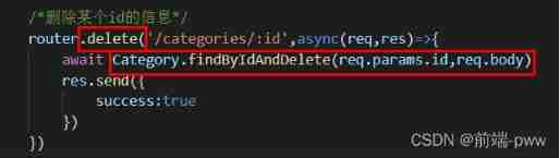
Management background --4, delete classification

Write a rotation verification code annotation gadget with aardio
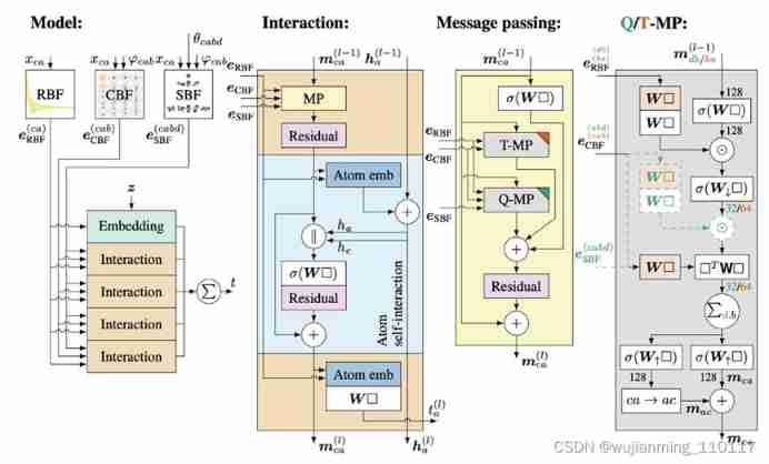
2021 geometry deep learning master Michael Bronstein long article analysis
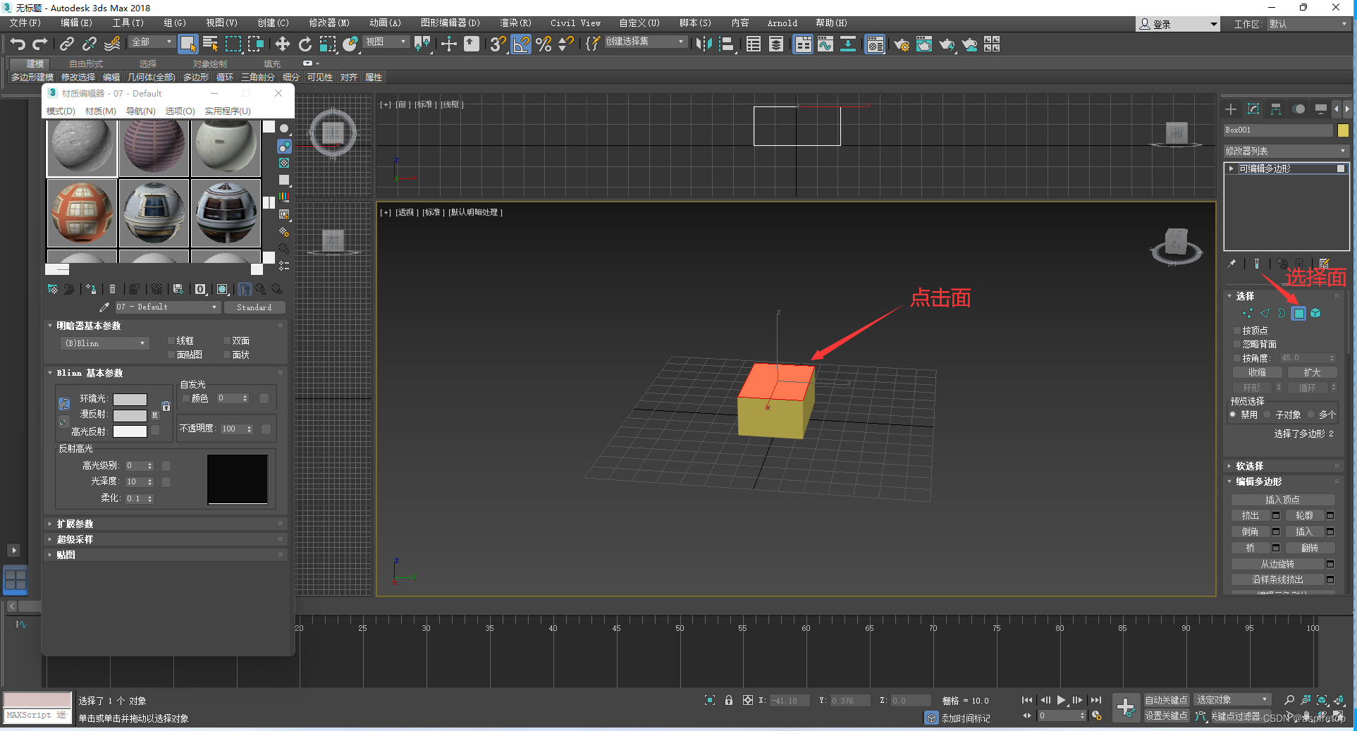
3DMax指定面贴图
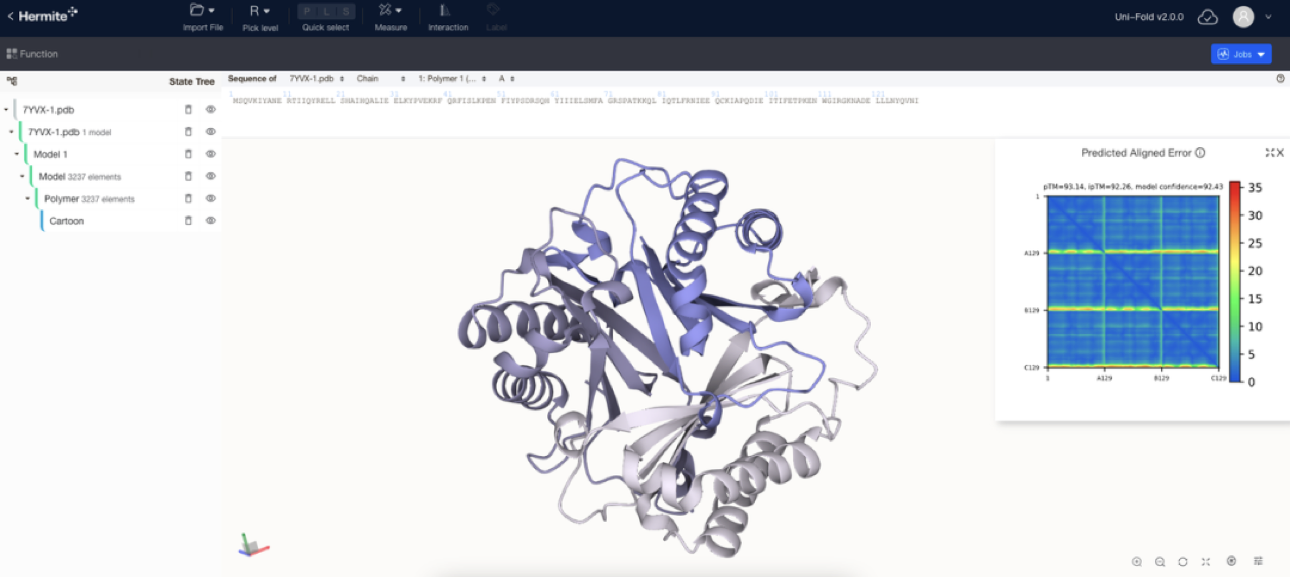
AI 企业多云存储架构实践 | 深势科技分享

2500个常用中文字符 + 130常用中英文字符
Management background --1 Create classification
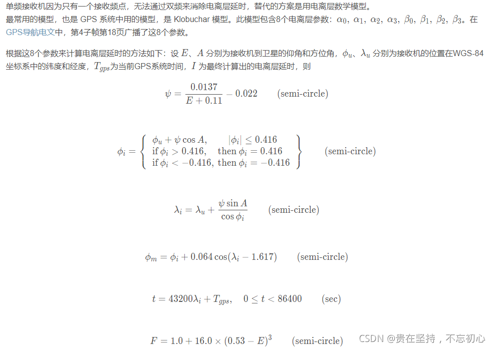
GPS from entry to abandonment (XIV), ionospheric delay
![[MySQL] online DDL details](/img/7e/97098d7ed5802c446bbadaf7035981.png)
[MySQL] online DDL details

Oracle control file and log file management
随机推荐
ZABBIX proxy server and ZABBIX SNMP monitoring
C # realizes crystal report binding data and printing 4-bar code
High precision face recognition based on insightface, which can directly benchmark hongruan
Kohana database
保存和检索字符串
Management background --1 Create classification
小常识:保险中的“保全”是什么?
Is it important to build the SEO foundation of the new website
Huawei has launched attacks in many industries at the same time, and its frightening technology has made European and American enterprises tremble
设置状态栏样式Demo
Some problems about the use of char[] array assignment through scanf..
GPS from getting started to giving up (19), precise ephemeris (SP3 format)
hdu 4912 Paths on the tree(lca+馋)
2500个常用中文字符 + 130常用中英文字符
Adjustable DC power supply based on LM317
[10:00 public class]: basis and practice of video quality evaluation
Management background --3, modify classification
i.mx6ull搭建boa服务器详解及其中遇到的一些问题
解决项目跨域问题
[sdx62] wcn685x will bdwlan Bin and bdwlan Txt mutual conversion operation method