当前位置:网站首页>Real time clock (RTC)
Real time clock (RTC)
2022-07-05 06:07:00 【Bitongo】
List of articles
- One 、RTC brief introduction
- Two 、 The main features
- 3、 ... and 、 Function description
- Four 、RTC Register description
- 1. RTC High order of control register (RTC_CRH)
- 2. RTC Control register low (RTC_CRL)
- 3. RTC Prescaled load register (RTC_PRLH/RTC_PRLL)
- RTC Prescaled load register low (RTC_PRLL)
- 4. RTC Prescaler remainder register (RTC_DIVH / RTC_DIVL)
- 5. RTC Counter register (RTC_CNTH / RTC_CNTL)
- 6. RTC Alarm register (RTC_ALRH/RTC_ALRL)
- 7. RTC Register image
One 、RTC brief introduction
The real time clock is a separate timer .RTC The module has a set of counters that count continuously , Under the corresponding software configuration , It can provide the function of clock and calendar . Modify the value of the counter to reset the current time and date of the system .RTC Module and clock configuration system (RCC_BDCR register ) In the backup area , After system reset or wake up from standby mode ,RTC The settings and time of the . After the system reset , For backup registers and RTC Access to is prohibited , This is to prevent damage to the backup area (BKP) Unexpected write operations for .
Doing the following will enable the backup register and RTC The interview of :
● Set register RCC_APB1ENR Of PWREN and BKPEN position , Enable power supply and backup interface clock
● Set register PWR_CR Of DBP position , Enable backup registers and RTC The interview of .
Two 、 The main features
● Programmable pre frequency division coefficient : The maximum frequency division coefficient is 220.
● 32 Bit programmable counter , It can be used for long-term measurement .
● 2 A separate clock : be used for APB1 Interface PCLK1 and RTC The clock (RTC The frequency of the clock must be less than PCLK1 More than a quarter of the clock frequency ).
● You can choose from the following three RTC The clock source of :
─ HSE Clock divided by 128; ─ LSE Oscillator clock ;
─ LSI Oscillator clock section RTC The clock .
● 2 Independent reset type :
─ APB1 The interface is reset by the system ;
─ RTC The core ( Preassigned frequency counter 、 alarm clock 、 Counter and frequency divider ) Can only be reset by the backup domain
● 3 A dedicated maskable interrupt :
─ The alarm clock is broken , Used to generate a software programmable alarm interrupt .
─ Seconds interrupt , Used to generate a programmable periodic interrupt signal ( Up to 1 second ). ─ Overflow interrupt , Indicates that the internal programmable counter overflows and returns to 0 The state of .
3、 ... and 、 Function description
1. summary
RTC It consists of two main parts ( See the figure below ). The first part (APB1 Interface ) For and APB1 Bus connection . This unit also contains a set of 16 Bit register , It can be done by APB1 The bus reads and writes to it .APB1 Interface by APB1 Bus clock driver , Used with APB1 Bus interface .
Another part (RTC The core ) It consists of a set of programmable counters , It is divided into two main modules . The first module is RTC Prescaler module , It can be programmed to produce up to 1 Of a second RTC Time base TR_CLK.RTC The prescaler module of includes a 20 Bit programmable frequency divider (RTC Preassigned frequency counter ). If in RTC_CR The corresponding allowable bit... Is set in the register , In each TR_CLK In cycle RTC Create an interrupt ( Seconds interrupt ). The second module is a 32 Bit programmable counter , Can be initialized to the current system time . System time press TR_CLK Cycles are accumulated and stored in RTC_ALR The programmable time in the register is compared , If RTC_CR The corresponding allowable bit is set in the control register , When comparing matches, an alarm clock interrupt will be generated .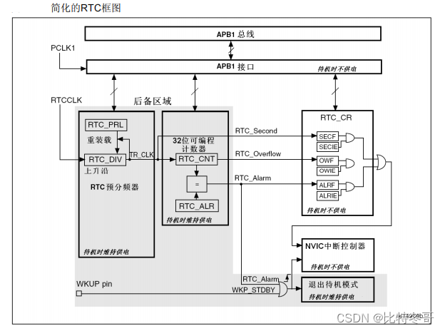
2. Reset process
except RTC_PRL、RTC_ALR、RTC_CNT and RTC_DIV Out of register , All system registers are asynchronously reset by system reset or power reset .
RTC_PRL、RTC_ALR、RTC_CNT and RTC_DIV The register can only be reset by the backup domain reset signal .
3. read RTC register
RTC The nucleus is completely independent of RTC APB1 Interface .
Software passed APB1 Interface access RTC Prescaled value of 、 Counter value and alarm value . however , The relevant readable registers are only associated with RTC APB1 Clock resynchronization RTC The rising edge of the clock is updated .RTC So is the logo .
It means , If APB1 The interface has been closed , And the read operation has just been restarted APB1 after , Before the first internal register update , from APB1 Read on RTC The register value may be corrupted ( Usually read 0). This can happen under the following circumstances :
● System reset or power reset occurs
● The system has just woken up from standby mode
● The system has just woken up from shutdown mode
In all the above cases ,APB1 When the interface is disabled ( Reset 、 No clock or power failure )RTC The core remains in operation .
therefore , If reading RTC When the register ,RTC Of APB1 The interface was once in a forbidden state , Then the software must first wait RTC_CRL In register RSF position ( Register synchronization flag ) Set by hardware ’1’.
notes : RTC Of APB1 The interface is not affected WFI and WFE And other low-power modes
4. To configure RTC register
You have to set RTC_CRL In register CNF position , send RTC After entering configuration mode , Can write RTC_PRL、RTC_CNT、RTC_ALR register .
in addition , Yes RTC Write to any register , Must be performed after the previous write operation . By querying RTC_CR In register RTOFF Status bit , Judge RTC Whether the register is being updated . Only when the RTOFF The status bit is ’1’ when , To write RTC register .
The configuration process :
- Inquire about RTOFF position , until RTOFF The value of a ’1’
- Set up CNF The value is 1, Enter configuration mode
- To one or more RTC Register for write operations
- eliminate CNF Sign a , Exit configuration mode
- Inquire about RTOFF, until RTOFF A into ’1’ To confirm that the write operation has been completed .
Only when the CNF When the flag bit is cleared , Write operation can be carried out , This process requires at least 3 individual RTCCLK cycle .
5. RTC Flag setting
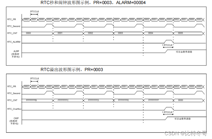
In every one of them RTC In the clock cycle of the core , change RTC Set before counter RTC Second sign (SECF). When the counter reaches 0x0000 The last one before RTC In the clock cycle , Set up RTC Overflow sign (OWF). When the value of the counter reaches the value of the alarm register, add 1(RTC_ALR+1) Previous RTC In the clock cycle , Set up RTC_Alarm and RTC Alarm sign (ALRF).
Yes RTC The writing operation of the alarm clock must use one of the following processes and RTC Second flag synchronization :
● Use RTC The alarm clock is broken , And modify in the interrupt handler RTC Alarm clock and / or RTC Counter .
● wait for RTC In the control register SECF Bit is set , Change again RTC Alarm clock and / or RTC Counter .
Four 、RTC Register description
1. RTC High order of control register (RTC_CRH)
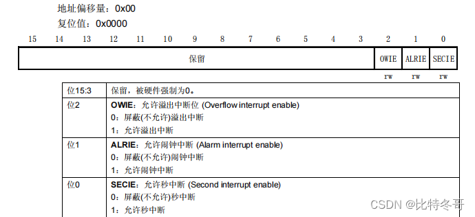
These bits are used to mask interrupt requests .
Be careful : After the system is reset, all interrupts are shielded , So you can write RTC Register to ensure that there are no pending interrupt requests after initialization . When the peripheral is completing the previous write operation ( Sign a RTOFF=0), Not right RTC_CRH Register for write operations .
RTC The function is controlled by this control register . Some bit write operations must be completed through a special configuration process
2. RTC Control register low (RTC_CRL)
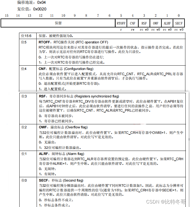
RTC The function of is controlled by this control register . When the current write operation has not been completed (RTOFF=0 when ), Can't write RTC_CR register .
notes :
- Any flag bit will remain suspended , Until appropriate RTC_CR The request bit is reset by software , Indicates that the requested interrupt has been accepted .
- Disable all interrupts during reset , No pending interrupt requests , It can be done to RTC Register for write operations .
- When APB1 When the clock is not running ,OWF、ALRF、SECF and RSF Bits are not updated .
- OWF、ALRF、SECF and RSF Bits can only be set by hardware , Reset by software .
- if ALRF=1 And ALRIE=1, It is allowed to generate RTC Global interrupt . If in EXTI It is allowed to generate EXTI Line 17 interrupt , It is allowed to generate RTC Global interrupts and RTC The alarm clock is broken .
- if ALRF=1, If in EXTI In the controller EXTI Line 17 Interrupt mode of , It is allowed to generate RTC The alarm clock is broken ; If in EXTI In the controller EXTI Line 17 The pattern of events , Then a pulse will be generated on this line ( Will not produce RTC The alarm clock is broken ).
3. RTC Prescaled load register (RTC_PRLH/RTC_PRLL)
The prescaled load register is used to save RTC Period count value of prescaler . They receive RTC_CR The register of RTOFF Bit protection , Only when the RTOFF The value is ’1’ Write operation is allowed when .
RTC Prescaled load register high (RTC_PRLH)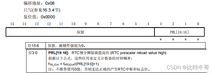
RTC Prescaled load register low (RTC_PRLL)
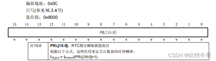
notes : If the input clock frequency is 32.768kHz(fRTCCLK), This register writes 7FFFh The available period is 1 Second signal .
4. RTC Prescaler remainder register (RTC_DIVH / RTC_DIVL)
stay TR_CLK Every cycle of ,RTC The value of the counter in the prescaler will be reset to RTC_PRL Register value . Users can read RTC_DIV register , To obtain the current value of the prescaler counter , Without stopping the work of the frequency division counter , So as to obtain accurate time measurement . This register is a read-only register , Its value is RTC_PRL or RTC_CNT Deposit
After the value in the filter changes , Reload by hardware .
RTC Prescaler remainder register high (RTC_DIVH)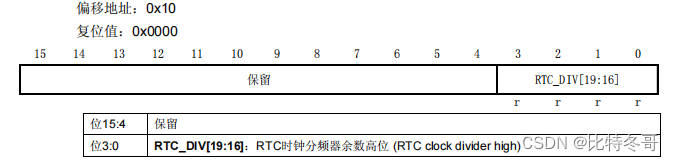
RTC Prescaler remainder register low (RTC_DIVL)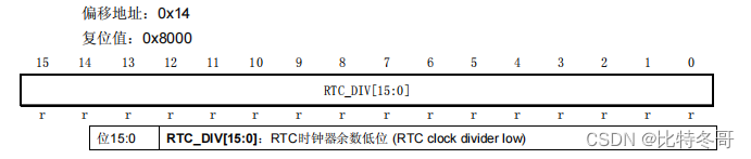
5. RTC Counter register (RTC_CNTH / RTC_CNTL)
RTC The nucleus has one 32 Bit programmable counter , There are two 16 Bit register access . The counter is generated by prescaler TR_CLK The time reference is used for counting .RTC_CNT The register is used to store the count value of the counter . They suffer from RTC_CR Of position RTOFF Write protect , Only when the RTOFF value by ’1’ when , Allow write operations . In the high or low register (RTC_CNTH or RTC_CNTL) Write operations on , It can be directly loaded into the corresponding programmable counter , And reload
RTC Preassigned frequency counter . When reading , Directly return the count value in the counter ( system time ).
RTC Counter register high (RTC_CNTH)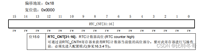
RTC Counter register low (RTC_CNTL)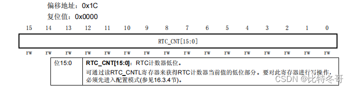
6. RTC Alarm register (RTC_ALRH/RTC_ALRL)
When the value of the programmable counter is equal to RTC_ALR Medium 32 When the bit values are equal , That is, trigger an alarm event , And produce RTC The alarm clock is broken . This register is affected by RTC_CR In the register RTOFF Bit write protection , Only when the RTOFF The value is ’1’ when , Allow write operations .
RTC Alarm register high bit (RTC_ALRH)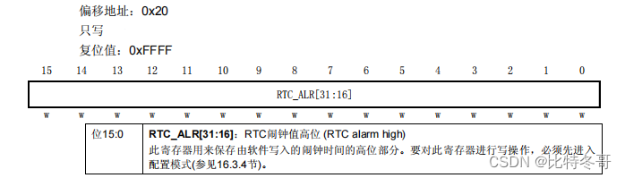
RTC Alarm register low (RTC_ALRL)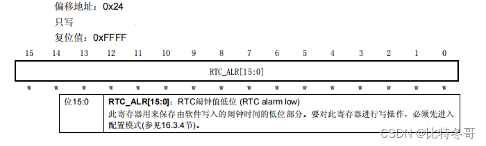
7. RTC Register image
RTC The register is 16 Bit addressable register , The details are as follows :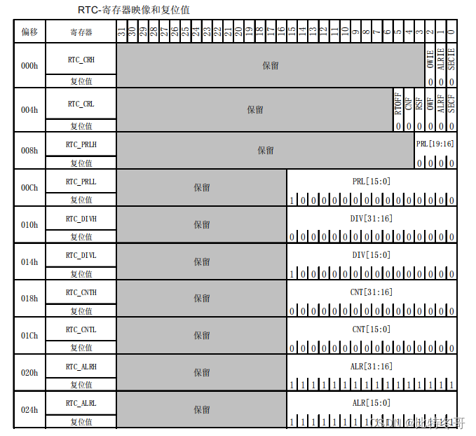
边栏推荐
- Daily question 1688 Number of matches in the competition
- Introduction to convolutional neural network
- 剑指 Offer II 058:日程表
- Sword finger offer 53 - ii Missing numbers from 0 to n-1
- Spark中groupByKey() 和 reduceByKey() 和combineByKey()
- The connection and solution between the shortest Hamilton path and the traveling salesman problem
- Codeforces Round #732 (Div. 2) D. AquaMoon and Chess
- CCPC Weihai 2021m eight hundred and ten thousand nine hundred and seventy-five
- 【实战技能】如何做好技术培训?
- 1.14 - 流水线
猜你喜欢
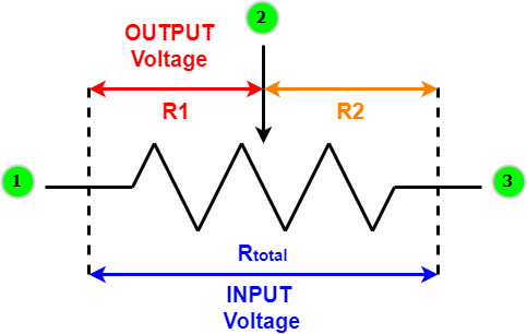
Overview of variable resistors - structure, operation and different applications
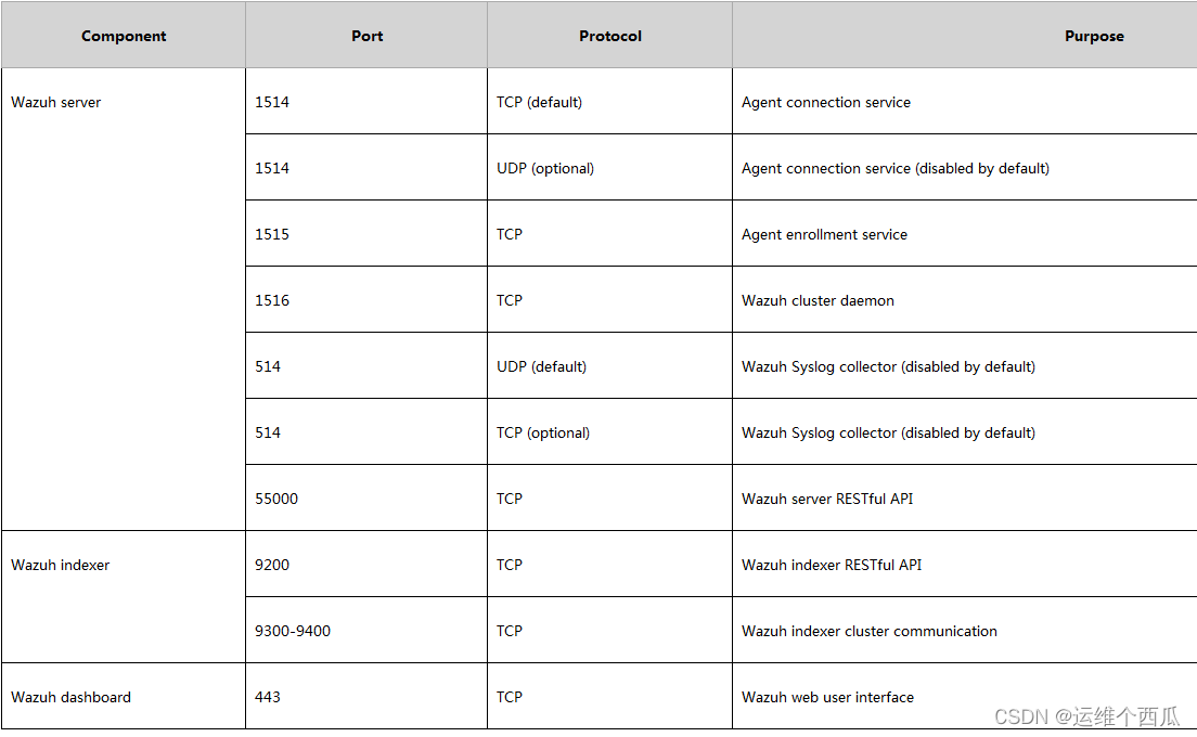
Wazuh開源主機安全解决方案的簡介與使用體驗
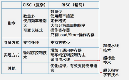
1.13 - RISC/CISC
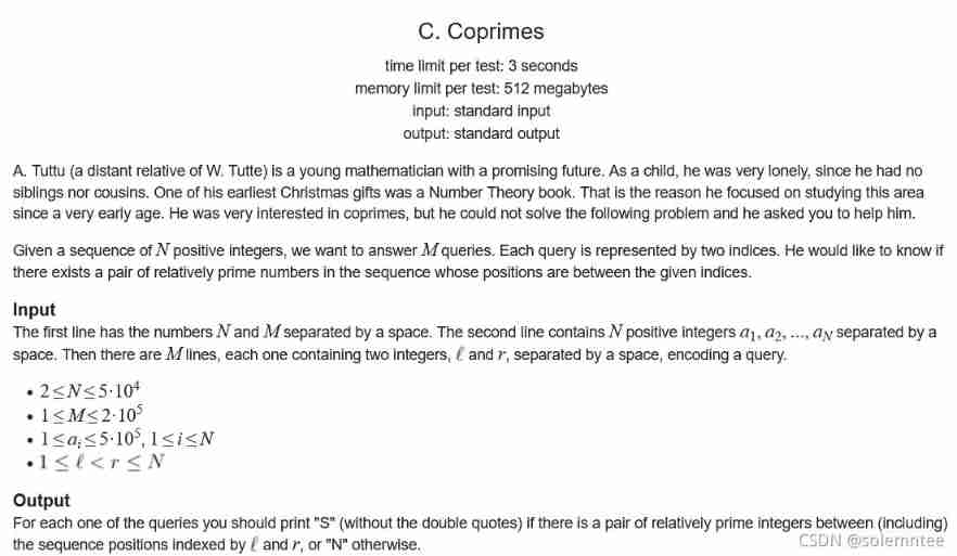
2017 USP Try-outs C. Coprimes
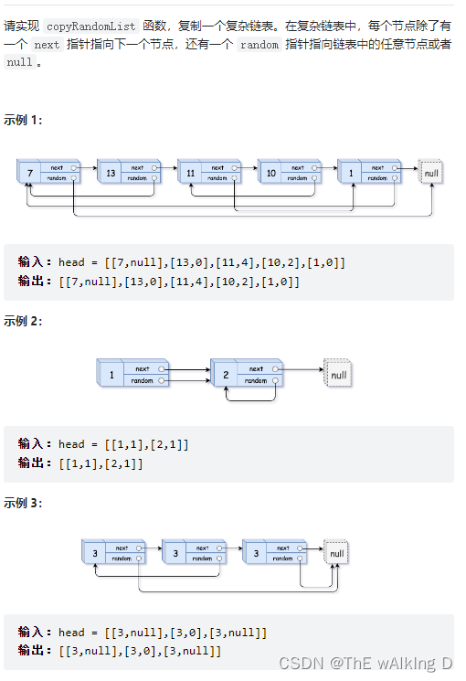
Sword finger offer 35 Replication of complex linked list
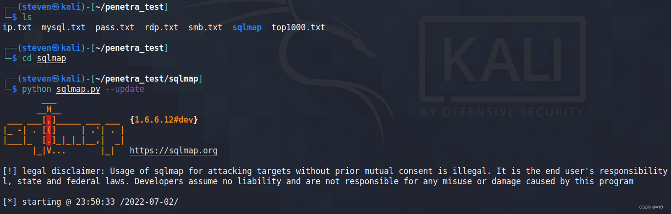
SQLMAP使用教程(一)
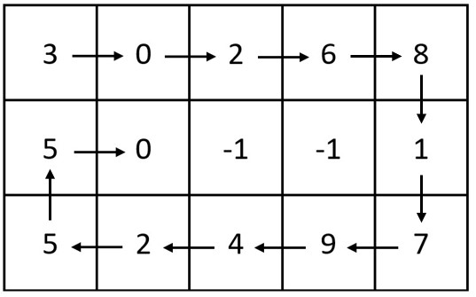
leetcode-6111:螺旋矩阵 IV

RGB LED infinite mirror controlled by Arduino
Implement an iterative stack
中职网络安全技能竞赛——广西区赛中间件渗透测试教程文章
随机推荐
开源存储这么香,为何我们还要坚持自研?
【Rust 笔记】13-迭代器(下)
【Jailhouse 文章】Jailhouse Hypervisor
The connection and solution between the shortest Hamilton path and the traveling salesman problem
Individual game 12
Sword finger offer 05 Replace spaces
RGB LED infinite mirror controlled by Arduino
实时时钟 (RTC)
Daily question 2013 Detect square
AtCoder Grand Contest 013 E - Placing Squares
927. 三等分 模拟
2022年貴州省職業院校技能大賽中職組網絡安全賽項規程
LVS简介【暂未完成(半成品)】
Analysis of backdoor vulnerability in remote code execution penetration test / / phpstudy of national game title of national secondary vocational network security B module
QT判断界面当前点击的按钮和当前鼠标坐标
可变电阻器概述——结构、工作和不同应用
Wazuh开源主机安全解决方案的简介与使用体验
【Rust 笔记】14-集合(上)
[rust notes] 13 iterator (Part 2)
[jailhouse article] look mum, no VM exits