当前位置:网站首页>Edcircles: a real time circle detector with a false detection control translation
Edcircles: a real time circle detector with a false detection control translation
2022-07-06 03:22:00 【qq_ forty-three million one hundred and thirty-three thousand o】
The title of the paper :EDCircles: A real-time circular detector with error detection control
Abstract
We propose a real-time , Nonparametric circle detection algorithm , High detection rate , Produce accurate results , And control the number of wrong circle detection . The algorithm makes use of the continuous ( connected ) Edge segment set , That is, parameterless edge drawing (EDPF) Algorithm ; Hence the name EDCircles. The algorithm first uses EDPF The algorithm performs edge segmentation on a given image , Then divide the edge into segments . Convert the detected line segment into an arc , Two heuristic algorithms are used to splice arcs , Candidate circles and near circular ellipses are detected . Finally, the candidate objects are verified through the reverse verification step of Helmholtz principle , This method eliminates error detection , Only valid circles and near circular ellipses are left . We have shown through experiments that ,edcircle Work in real time (640 x 480 Graphic 10-20 millisecond ), High detection rate , Produce accurate results , It is very suitable for the next generation of real-time vision applications , Including automatic detection of industrial products , Pupil detection , Ring traffic sign detection, etc .
brief introduction
The detection of circular objects in digital images is image processing [1] And computer vision [2] An important and recurring problem in , Especially in the automatic detection of industrial products [3]、 Line drawing image aided vectorization [4,5]、 Pupil and iris detection [6-8]、 Circular traffic sign detection [9-11] There are many applications in automation problems, such as others .
The ideal circle detection algorithm is fixed for the internal parameters of all images , That is, there is no need to optimize the parameters of different images , Very fast ( Real time if possible ), It can detect multiple large and small circles , Can handle synthetic 、 Natural and noisy images , High detection rate , High accuracy , Little or no error detection . The circle detection algorithm proposed in this paper satisfies all these properties .
Traditionally, the most popular circle detection technology is based on the famous circle Hough transform (CHT)[12-16]. These techniques first use traditional edge detectors ( Such as Canny[17]) Calculate the edge mapping of the image , Map the edge pixels to the three-dimensional Hoff circle space (x, y, r), And extract a circle containing a certain number of edge pixels . be based on cht Our technology is not only very slow but also requires memory , And there will be many false detections , Especially in the presence of noise . Besides , Many parameters of these methods must be preset by the user , This greatly limits their use .
In order to overcome based on cht Limitations of classical methods , Many variants have been proposed , Including probability HT[18,19], Random HT[20,21], Fuzzy HT[22] etc. . It's also based on HT And hypothetical filtering [23-25].Alk These methods try to correct CHT Different disadvantages of , But you still need memory , Slow to use in real-time applications .
In addition to based on cht Out of the way , There are also several randomized circle detection algorithms .Chen wait forsomeone [26] A random circle detection method is proposed (RCD) Algorithm , The algorithm randomly selects from the edge mapping of the image 4 Pixel , Use the distance criterion to judge whether there are possible circles in the image . then , They use a step of collecting evidence to test whether the candidate circle is a real circle .RCD Produce good results , But slower . lately ,Chung wait forsomeone [27,28] An efficient sampling and thinning strategy is proposed , To speed up RCD The speed of , Improve RCD Accuracy of results . Although new RCD variant GRCD-R、GLRCD-R[28] It has good detection rate and accurate results , But there is still a big gap from real-time . Besides , all rsd - Variants are made up of traditional edge detectors ( Such as Sobel Filter or Canny Edge detector ) The calculated image edge works on the map , Many parameters of these edge detectors must be set by the user .
In recent years , The application of genetic algorithm and evolutionary computing technology in circle detection has become a research hotspot [29-36].Ayala-Ramirez wait forsomeone [30] A genetic algorithm for circle detection is proposed (GA), The algorithm can detect multiple circles , But it is often impossible to detect small or imperfect circles .Dasgupta etc. [31-33] A swarm intelligence technology for circle detection is developed —— Adaptive bacterial foraging optimization (ABFO). The algorithm has good effect , But sensitive to noise .Cuevas Et al. Used discrete differential evolution (DDE) Optimize [34]、 Harmonious search optimization (HSA)[35] And clonal selection algorithm (CSA)[36] Artificial immune system optimization technology for circulation detection . Although these evolutionary computing techniques have good detection rate and accurate results , But it usually requires multiple runs to detect multiple circles , Slower , Not suitable for real-time applications . And RCD Algorithm is the same , These algorithms are also applicable to the edge map pre calculated by the traditional edge detection algorithm .
Frosio wait forsomeone [37] A real-time circle detection algorithm based on maximum likelihood is proposed . This method is fast , It can detect partially occluded circular objects , But the radius of the detected circle needs to be defined in advance , This greatly limits its application .Wu Et al. Proposed a cycle detection algorithm , The algorithm 640 x 480 Run on the image 7 frame /s. The author claims to have achieved a high success rate , But there is not much experimental validation to support their claim .Zhang wait forsomeone [38] An ellipse detection algorithm that can be used for real-time face detection is proposed .Liu wait forsomeone [39] An ellipse detector for noisy images is proposed ,Prasad wait forsomeone [40] An ellipse detector using edge curvature and concave convex information is proposed . Although these two algorithms have produced good results , But they are slower , Not suitable for real-time applications .
Vizireanu etc. [42-44] Use mathematical morphology to decompose the shape of the image , Different shapes and patterns in the image are recognized by using the morphological shape decomposition representation of the image . Although their algorithm detects the general shape in the image very well , But they are not suitable for real-time applications .
Problems about reverse arc detection , See below . lately ,Patraucean wait forsomeone [45,46] A nonparametric ellipse detection algorithm is proposed , The algorithm is based on desolation neux wait forsomeone [58] The reverse frame of . The author expanded Grompone von Gioi wait forsomeone [63] Line segment detector (LSD), Detect arcs and elliptical arcs in a given image without any parameters , Simultaneous utilization Helmholtz principle [58] Control the number of error detection . then , They use the proposed algorithm ( Name it ELSD[46]) To detect and identify Bubble Tags[47].
In this paper , We propose a real-time (640 x 480 On the image 10-20 millisecond ), Nonparametric circle detection algorithm , High detection rate , Produce accurate results , And there is a reverse verification step , Because of the Helmholtz principle , Let it control the number of error detection . The algorithm makes use of the continuity generated by our nonparametric edge segment detector ( connected ) Edge segment set , That is, parameterless edge drawing (EDPF) [48-53]; Hence the name EDCircles[54,55]. Given an input image ,EDCircles use first EDPF Calculate the edge segment of the image . Next , Use segment detectors EDLines[56,57] Convert the obtained edge segment into line segment . Then convert the calculated line into an arc , And use two heuristic algorithms to combine , Generate many candidate rings and near circular ellipses . Last , adopt Helmholtz Candidate results of principle verification [58-63], This principle eliminates error detection , Only valid circles and near circular ellipses are left .
2. Proposed algorithm :EDCircles
EDCircles Follow several steps to calculate the circle in a given image . The basic idea is to extract line segments in the image , Convert it to an arc , Then combine these arcs to detect circles and near circular ellipses .EDCircles The general outline of the algorithm is in the algorithm 1 Give in , We will describe in detail in the following sections EDCircles Every step of .
Algorithm 1 EDCircles The steps of the algorithm .
- utilize EDPF Detect edge segments , Extract complete circles and ellipses .
- Convert the remaining edge segments into segments .
- Detect arc segments by merging segments .
- Adding arcs to detect circle candidates .
- Add the remaining arcs , To detect ellipse candidates close to a circle .
- Use Helmholtz principle to verify candidate circles / The ellipse .
- Output the remaining valid circles / The ellipse .
2.1. Edge segmentation algorithm based on free edge rendering parameters
Given an image ,EDCircles The first step is to detect the edge segment in the image . To achieve this , We use our recently proposed real-time edge / Edge segmentation detector , Edge drawing (ED)[48-51]. Different from the traditional edge detector , for example Canny[17], It recognizes a group of potential edge pixels in the image , And through non maximum inhibition 、 Lag threshold 、 Operations such as erosion eliminate non edge pixels ,ED Follow a proactive approach , First, identify a group of points in the image , It's called an anchor , Then use an intelligent router to connect these anchors ; in other words ,ED It's actually drawing edges in the image .ED It not only outputs binary edge images similar to traditional edge detectors , And the output result is a group of edge segments , Each edge segment is a continuous ( Connect ) Pixel chain [49].
ED There are many parameters that users must set , This requires tuning for different types of images ED Parameters of . Ideally , People want to have a real-time edge / Edge segmentation detector , It runs on a fixed set of internal parameters for all types of images , No parameter tuning is required . In order to achieve this goal , We are going to ED Combined with a reverse edge verification mechanism based on Helmholtz principle [58-60], A real-time nonparametric edge segmentation detector is obtained , We call it nonparametric edge rendering (EDPF)[52,53].EDPF It works on ED At the extreme value of all parameters of ED, It detects all possible edge segments in a given image , There are many false positives . then , We verify the extracted edge segment by Helmholtz principle , It eliminates error detection , Only the edge segment of perceptual meaning is left relative to a reverse method .
chart 1(a) Shows a 424 x 436 Grayscale composite image , One of them is 4 A big circle covered by rectangular blocks 、 One being 3 A small ellipse covered by rectangular blocks 、 A small circle 、 An ellipse and an arbitrary polygon like object . When the image is input EDPF when , As shown in the figure 1(b) Edge segment shown . Each color in the edge graph represents a different edge segment , Each edge segment is a continuous chain of pixels . For this image ,EDPF stay 2.2 GHz Intel 2670QM CPU Of PC Only in 3.7 ms Internal output 15 Edge segments . Pay attention to the high quality of the edge map , All details are clearly visible .
Each edge segment tracks the boundaries of one or more objects in the graph . Although the boundary of an object can be tracked by a single edge segment , But little circle 、 Elliptical and polygonal objects are shown in the figure 1(b) Shown , It is also possible that the boundary of an object is tracked by multiple different edge segments . This is the case of the great circle , Because the boundary of the circle is tracked by four different edge segments , The small blocked ellipse is tracked by three different edge segments . The result depends entirely on the structure of the object , The amount of obstruction and noise in the image . in other words , There is no way to tell the edge segment how to track the boundary of the object in a given image in advance .
From the picture 1 Can be seen in , In some cases , For example, small circle 、 Ellipses and polygons , The whole boundary of the object in the image will return in the form of a closed curve ; in other words , The edge segment starts with a pixel on the boundary of the object , Track its entire boundary , And end where it starts . in other words , The first pixel and the last pixel of the edge segment are adjacent . Pictured 1 Shown , Such a closed edge segment is likely to follow the circle 、 The boundary motion of an ellipse or polygon . therefore , The first step after detecting edge segments , We check all the edge segments , Select the closed edge segment , See if the closed edge segment tracks the entire boundary of a circle or an ellipse .
The processing of closed edge segments follows a very simple idea : We first use the least square circle fitting method [64] Fit a circle into the entire pixel list of the edge segment , And calculate the root mean square error . If the circle fitting error , That is, the root mean square error is less than a certain threshold ( Fixed in 1.5 Pixels ), Then add the circle to the candidate circle list . The small fitting error of a circle does not mean that this edge is a circle ; It's just a candidate , It needs to pass the circle verification of Helmholtz principle to return to a real circle . The first 2.6 Section describes the details of circle verification .
If the circle fitting fails , Then we try to fit the pixels from an ellipse to the edge segment . We use [65] Ellipse fitting algorithm described in , It returns a form of Ax2 + Bxy +Cy+Dx+ Ey +F= 0 Elliptic equation of . If the ellipse fitting error , That is, the root mean square error is less than a certain threshold ( This algorithm fixes it as 1.5 Pixels ), Then add the ellipse to the ellipse candidate list , The ellipse also needs to pass the verification of Helmholtz principle , Then return as a real ellipse .
If the edge segment is accepted as a circle or an ellipse candidate , It will be deleted from the list of edge segments , No further processing . otherwise , This edge segment will be used for further processing together with other non closed edge segments .
2.2. Convert edge segments to line segments
After removing the closed edge segment , Take it as a candidate circle or ellipse , Convert the remaining edge segments into line segments ( The rest of this paper is simply called line segment ). The motivation for this step comes from the observation that any circular shape is approximated by a set of continuous lines ( Pictured 1 Shown ), These lines can be easily transformed into arcs through a simple post-processing step , Described in the next section .
Converting edge segments into a set of lines follows our line detector EDLines[56,57] The algorithm given in . The idea is , Start with a short line that meets a certain straightness standard , As long as the root mean square error is less than a certain threshold , namely 1 Pixel error , Just extend this line . Detail reference of segment extraction EDLines[56,57], We use Helmholtz The principle verifies the detected line segment , To eliminate invalid detection . however , stay EDCircles in , We don't verify the line after testing . The reason for this decision is our observation , because Helmholtz Principle line segment verification algorithm usually eliminates many short line segments , This may be valuable for the detection of small circles in the image . therefore , And EDLines The difference is , We do not exclude any detected line segments , Instead, all detected line segments are used for further processing and arc detection .
chart 1 Shown in Figure 1(a) Line extracted from the image shown . obviously , A circular object can be approximated by a set of continuous lines . In the next section , We will describe how to convert these lines into arcs by processing continuous lines .
2.3. Arc detection
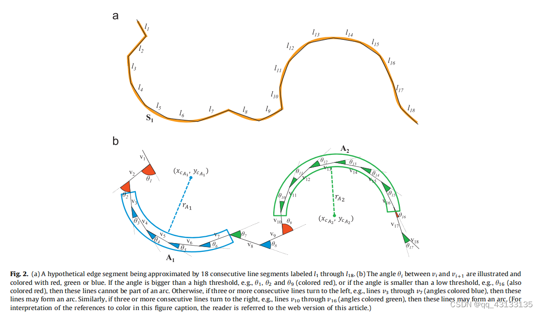
We define an arc as having at least three consecutive 、 A collection of straight lines turning in the same direction . According to this definition , We can detect the following arcs : Given a set of lines that make up the edge segment , Simply traverse these lines , Calculate the angle between continuous lines and the turning direction from one line to another . If at least three lines turn in the same direction , And the included angle between lines is between certain thresholds , Then these lines can form an arc .
chart 2 It shows that a hypothetical edge segment is 18 A continuous line segment approximates , Marked as I, To l18. To calculate the angle between two continuous lines , We just need to take each line as a vector , And calculate the dot product of the vector . Similarly , To calculate the direction of turning from one line to another , We just need to calculate the vector cross product , And use the symbol of the result as the turning direction .
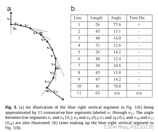
chart 3(a) Figure is given 1(b) The middle right blue vertical section is 11 Consecutive labels are v1 To v11 The result of the line segment approximation of . chart 3(b) Shows 11 Details of the line : Their length 、 The included angle between continuous lines and the turning direction from one line to another , among “+” To turn left ,“-” To the right .
Our arc detection algorithm is based on the following ideas : A group of lines should become potential arc candidates , They must have the same turning direction ( To the left or right ), And the included angle between continuous lines must be between a certain threshold . If the angle is too small , Let's assume that these two lines are collinear , So they can't be part of the arc ; If the angle is too large , We assume that these lines are part of a strictly rotating object , Such as a square 、 Rectangle, etc . For our current implementation , We fixed the low angle threshold to 6°, The high angle threshold is fixed to 60°. These values are obtained through experiments on various images containing various circular objects .
chart 2 The bottom of the figure depicts 2 The included angle between the continuous lines of the edge segment shown at the top , And the direction of turning from one line to another . Angles less than the low angle threshold or greater than the high angle threshold , Such as 01、θ2、θg and 916, Marked red ; All other angles are painted blue or green according to the change of direction . say concretely , If the next line turns left , This angle is painted blue , If the next line turns right , Then this angle is painted green .
These values are obtained through experiments on various images containing various circular objects . After calculating the angle and direction turning information , We simply traverse the line of an edge segment , Look for a group of at least 3 A collection of consecutive lines , These lines all turn in the same direction , And the turning angle from one line to the next line is between the low angle and high angle threshold . In the figure 2 in , Line v3 To v7 Meet our criteria , Is a potential candidate arc . Similarly ,v10 To v16 Rows form another candidate arc .
Given a set of at least three lines that meet the arc candidate constraints , We first try to use [64] The circle fitting algorithm in fits a circle to all the pixels that make up these lines . If the circle fitting is successful , That is, the root mean square error is less than 1.5 Pixels , Then you only need to add the extracted arc to the arc list , It's done. . otherwise , We start with a short arc consisting of only three lines , By fitting a new circle [64] Expand it line by line , Until the root mean square error exceeds 1.5 Pixels . here , The detected arc is added to the arc list , We continue to process the remaining lines to detect more arcs . Using this algorithm , We are in the picture 2 Two arcs are detected in : v 3 v_{3} v3 To v 7 v_{7} v7 An arc formed by a straight line A1, The center of the circle is ( X C A 1 , Y C A 1 X_{CA1}, Y_{CA1} XCA1,YCA1), The radius is r A 1 r_{A1} rA1. Again , v 10 v_{10} v10 To v 16 v_{16} v16 The straight line of forms an arc A2, The center of the circle is ( X C A 2 , Y C A 2 X_{CA2}, Y_{CA2} XCA2,YCA2), The radius is r A 2 r_{A2} rA2. In a complex image composed of many edge segments , We will have hundreds of arcs .
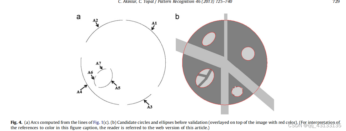
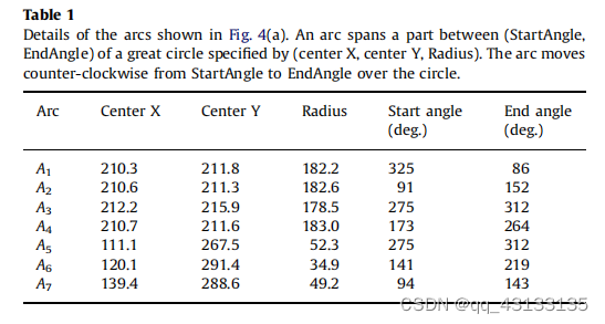
chart 4 Shows from figure 1 The arc calculated by the line of , surface 1 Details of these arcs are given . The arc spans the great circle ( center of a circle X, center of a circle Y, radius ) Part between ( Starting angle , End angle ). Suppose the arc moves counterclockwise from the start angle to the end angle on the big circle . With Az For example , The coordinates of the center of the circle (210.6,211.3), radius = 182.6 The great circle of from 91° To 152° Total coverage 61°.
2.4. Use arc connection to detect candidate circles
After calculating the arc , The next step is to add the arc to the candidate circle . Do that , We first sort all arcs in descending order of length , And start by extending the longest arc . The motivation for this decision comes from the observation that the longest arc is closest to a complete circle , So it must extend and complete a complete circle before other arcs . In the extension of the arc , Our idea is to find an arc with similar radius and near center , And collect a list of candidate arcs that may be combined with the current arc .
Given an arc Ai Extend into a complete circle , We check all detected arcs , And generate a set of possible and a Connecting candidate arcs . We have two criteria for determining arc connection :(1) Radius difference constraint :Ay And candidate arcs A The radius difference of must be within a certain threshold . among , If Az The radius of is less than A1 Of radius 25%, Then take Az As a candidate to join ; otherwise A2 Cannot be associated with Aj Connect . for example , If Ay The radius of is 100, Then all radii are 75 To 125 The arcs between can be used as candidate arcs for arc connection .(2) Center distance constraint :A1 Center of and candidate arc A2 The distance between the centers of must be within a certain threshold . say concretely , We demand Aj and A2 The distance between the centers of cannot exceed Al Of radius 25%. for example , If Ay The radius of is 100, Then all the center distances Ay center of a circle 25 Arcs within pixels can be used as candidate points for arc connection, and they also meet the radius difference construction .
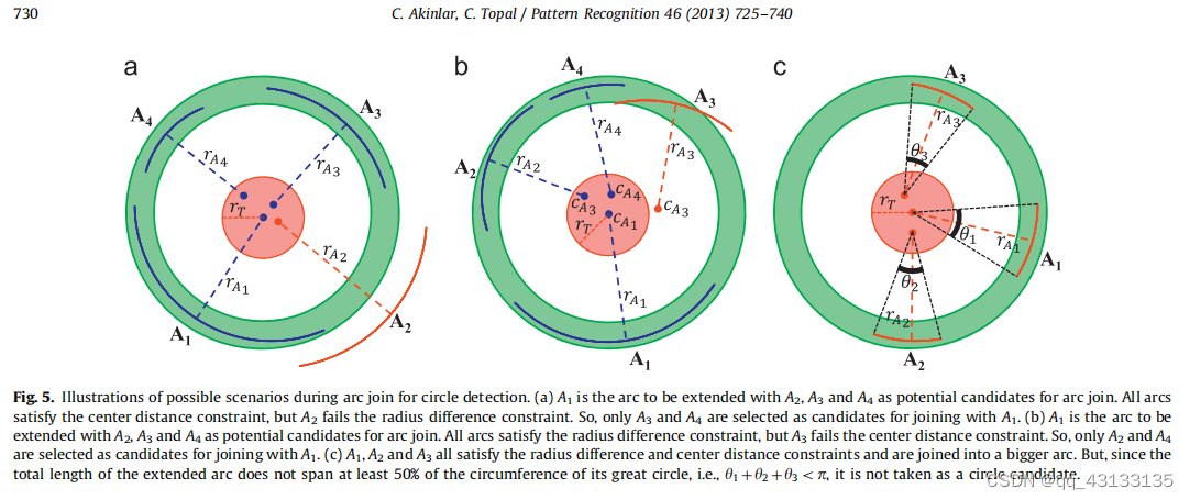
chart 5 Possible scenarios when detecting circles for arc connections . In the figure 5(a) in , We illustrate a situation , All potential candidate arcs satisfy the center distance constraint , But there is one that does not satisfy the constraint of radius difference . here ,A1 Yes, it will A2、A3 and A4 An arc that is extended as a potential candidate for arc connection . As shown in the figure , The centers of all arcs are very close ; namely A2、A3 and A4 From the center of to A1 The center distance is within the center distance threshold rt within , For radius difference constraint , Only A3 and A4 Satisfy , and A2 The radius of is not within the radius difference . So in the picture 5(a) in , Only arc segments are selected A3 and A4 As and A1 Connection candidates .
In the figure 5(b) in , We show a situation , All potential candidate arcs satisfy the radius difference constraint , But there is one that does not satisfy the center distance constraint . here A1 Is the arc to be extended ,A2、A3、A4 Is the potential object of arc connection . As shown in the figure , The radii of all arcs are very close , Therefore, both satisfy the constraint of radius difference . For the center distance constraint , Only A2 and A4 Satisfy , and A3 The center of does not reach the center distance threshold rt. So in the picture 5(b) in , Just choose A2 and A4 As and A1 Connected candidate arcs .
After calculating the candidate arc , The next step is to connect them one by one with the extended arc A1 Combine , By fitting a new circle to the pixels that make up the two arcs . We no longer try to connect in random order , But from any endpoint A1 The nearest arc at any endpoint of . The motivation for this decision comes from the observation , If the same big circle has more than one arc , It is best to extend from the nearest arc A The arc of begins to connect . In an effort to 5(a) For example , We will first A1 And A4 Connect , then A3 Connect . Similarly , In the figure 5(b) in , We will first connect A1, Then connect A2, Then connect A4.
When the arc A1 After unfolding with other arcs on the same big circle , In the last step, we decide whether to make the extended arc a candidate arc . ad locum , We think , If the span of an arc is at least of its great circumference 50%, Then we think of this arc as a circle . otherwise , Arc is left near circular ellipse detection . In an effort to 5(a) For example , When A1 And A4 and a When the connection , The extended arc will span its great circumference 50% above . So the extended arc should be a candidate for a circle . However , In the figure 5 in , When A1、A2 and A3 When connected , We observe that the extended arc does not span at least 50%, namely θ1 +θ2 +θ3 <π; therefore , An extended arc cannot be a candidate for a circle . The total arc span is calculated by simply looking at the ratio of the total number of pixels that make up the connecting arc to the circumference of the new fitting circle . If the proportion is greater than 50%, Then the extended arc is taken as the candidate circle .
To illustrate the above point , Here is how to deal with the diagram 4(a) And table 1 Seven arcs detailed in : We start with A1, The longest arc , As the arc to be extended ,A2, A3, A4, A5, A6 and A7 As the remaining arc . because A2、A3、A4 The radius of is A1 Of radius 25% within , And their center distance is within the center distance threshold , So only these three arcs are selected as candidate arcs . because A2 The endpoint of is closest A1, We're going to A1 and A2 Connect ( See chart 4(A)). stay A1 and A2 After connection , The extended arc will now be associated with A3 Connect , because A3 The endpoint of is now closest to the extended arc . The final will be A4 Connect . Because the final extended arc covers its big circle 50% above , Therefore, it is considered as a candidate circle . similarly , The next longest arc left is A5, So we try to use A6 and A7 Expand as the only remaining arc in the arc list A5. Only with A5 The candidate arcs for connection are A7, because A6 Radius of is not A5 Of radius 25% within .
2.5. Candidate near circular ellipse detection based on arc connection
The algorithm introduced in the previous section deals with the detection of perfect circle candidates . But this algorithm cannot detect ellipses that are close to circular . as everyone knows , According to the viewpoint of the camera , The circle looks slightly elliptical . therefore , Circle detection algorithm is particularly important for the detection of imperfect circular objects in images .
Arc connection and... For ellipse detection 2.4 The arc connection for perfect circle detection described in section is very similar . Given an arc to extend into an ellipse Aj, We examine the remaining arcs and generate a set of possible and A1 Candidate arcs connected into ellipses . For arc connection , We adopt and 2.4 Section the same two guidelines , But the constraints have been relaxed :(1) Radius difference constraint : If Az Radius and A1 The radius difference of 50%, Then take Az As a candidate for connection ; otherwise Az Unable to join A together . for example , If Ay The radius of is 100, Then all radii are 50 To 150 The arcs between can be used as candidate arcs for arc connection .(2) Center distance constraint : We demand A1 and A2 The distance between the centers of cannot exceed A1 Of radius 50%. for instance , If A1 The radius of this is 100, Then all arcs including the center of the circle . With A1 Central 50 Pixels are used as candidate points for arc connection , Suppose they also satisfy the radius difference constraint .
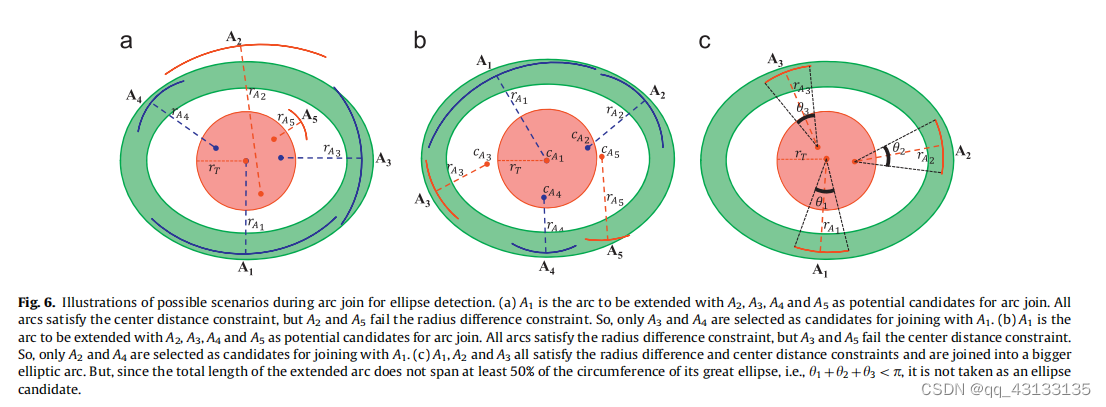
chart 6 Possible scenarios for arc connected ellipse detection . In the figure 6(a) in , We show a situation , All potential candidate arcs satisfy the center distance constraint , But there are two that do not satisfy the constraint of radius difference . here ,A1 Yes, it will A2、A3、A4、A5 Arcs extended as potential objects connected by arcs . As shown in the figure , The centers of all arcs are very close ; namely A2、A3、A4、A5 From the center of to A The center distance is within the center distance threshold rr Inside . For radius difference constraint , Only A3 and A4 Satisfy , and A2 and A5 The radius of is not within the radius difference . So in the picture 6(a) in , Only arc segments are selected A3 and A4 As and A1 Connection candidates .
In the figure 6(b) in , We show a situation , All potential candidate arcs satisfy the radius difference constraint , But there are two that do not satisfy the center distance constraint . here A1 Is the arc to be extended ,A2、A3、A4、A5 Are potential objects connected by arcs . As shown in the figure , The radii of all arcs are very close , Therefore, both satisfy the constraint of radius difference . For the center distance constraint , Only A2 and A4 Satisfy , and A3 The center and A5 The center of is not at the center distance threshold rt within , So in the picture 6(b) in , Just choose A2 and A4 As and A1 Connected candidate arcs .
After calculating the candidate arc , The next step is to use [65] Ellipse fitting algorithm in , Fit a new ellipse on the pixels that make up the two arcs , Connect them one by one with the extended arc A1 Merge . If the root mean square error is less than 1.5 Pixels , Successful connection ; otherwise , It will fail . We no longer try to connect in random order , But from any endpoint A1 Start of the nearest arc at any endpoint of . The motivation for this decision comes from observation , If there are multiple arcs that are part of the same large ellipse , It is best to extend from the closest arc A1 The arc of begins to connect . In an effort to 6(a) For example , We will first A1 And a Connect , then A4 Connect . Again , In the figure 6(b) in , We will first A1 And Az Connect , then A4 Connect .
When the arc A1 After unfolding with other arcs on the same large ellipse , In the last step, we decide whether to make the extended arc an ellipse candidate . ad locum , We think , If the extended arc crosses the circumference of its large ellipse by at least 50%, So let's make this arc an ellipse candidate . otherwise , The arc will be excluded from further processing . In an effort to 6(a) For example , When A1 And As and A4 When the connection , The extended arc span exceeds the circumference of its large ellipse 50%. So the extended arc is an ellipse candidate . However , In the figure 6 in , When A1、A2 and a When connected , We observe that the extended arc does not span at least its large ellipse 50% The circumference of , namely θ1 +θ2+θ3 < π. therefore , The extended arc is not considered an elliptical candidate . The total arc span is calculated by simply looking at the ratio of the total number of pixels that make up the connecting arc to the circumference of the newly fitted ellipse . If the proportion is greater than 50%, Then the extended arc is regarded as an ellipse candidate .
To illustrate the above point , Here is how to deal with the diagram 4(a) And table 1 The remaining three arcs detailed in ,A5, A6 and A7: because A5 Is the longest arc , We try to A6 and A7 As a candidate extension A5. because A5 and A6 The radius of is A5 Of radius 50% within , And the center distance is within the center distance threshold , Therefore, both arcs are considered as candidate arcs . Then we try to connect A5 and A6, because A6 The endpoint of is closest A5( See chart 4(a)). Last , take A7 Connect . Because the final extended arc covers its large ellipse 50% above , Therefore, it is considered as a candidate ellipse .
chart 4(b) It shows the figure 1(a) All circle and ellipse candidate points of the image are superimposed in red at the top of the image . We have 3 A circle and 2 An ellipse candidate , The small circle 、 Small ellipse and small polygon objects become candidates in the first step of the algorithm , Because their edge segments draw their entire boundary into a closed curve ; In step four , The great circle will A1、A2、A3 and A4 The arcs merge into a perfect circle , Become a candidate arc ; Step five , Set the arc A5、A6 and A7 Merge into an ellipse , Occluded ellipses become candidate ellipses . Now? , all 5 All candidates must pass Helmholtz principle ( This will be described in the next section ) Validation of the , Then it is returned to the true positive test .
2.6. Verify the circle and ellipse with Helmholtz principle
In the first two sections , We described EDCircles How to connect arcs into circle or ellipse candidates . Just because some arcs can be connected into circles and ellipses does not mean that all candidates are effective detection . therefore , As a last step ,EDCircles Use circle and ellipse verification algorithm to eliminate invalid detection , Only valid circles and ellipses are returned .
In the discussion EDCircles Before using the circle and ellipse Verification Algorithm , We first need to define the Helmholtz principle , Lay the foundation for its reverse validation framework , And describe how to use it to detect meaningful alignment in a given image , That's line segments . Then the line verification technology is applied to circle and ellipse verification .
Helmholtz principle simply put , A geometric structure should be meaningful in perception , This structure ( Grouping or Gestalt ) Expectations must be low in random situations [59,60]. This is the opposite approach , The object is detected as an outlier of the background model . Such as desolation [60] Shown , A suitable background model is that all pixels are independent . They show that the simplest of these models is Gaussian white noise . let me put it another way , In Gaussian white noise image [60] There is no meaningful structure in .
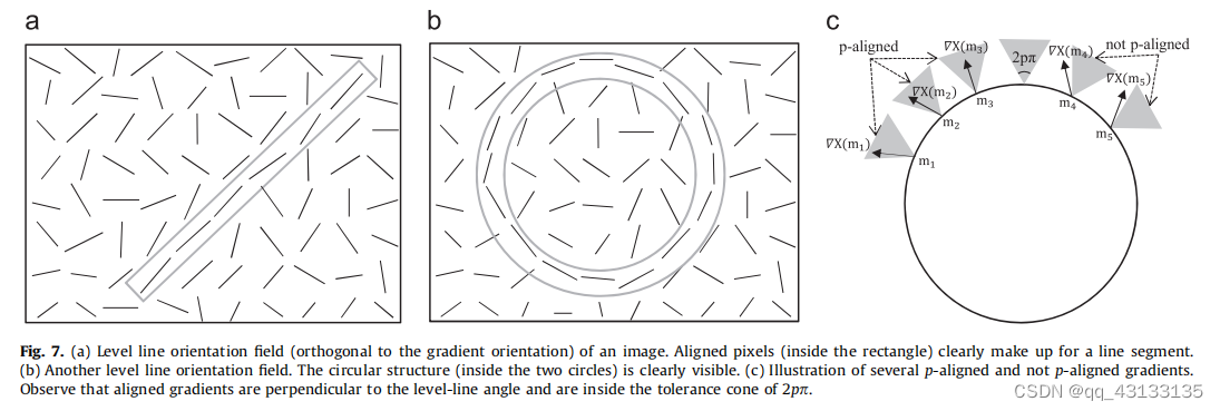
solneux Used by others Helmholtz Principle find meaning alignment in a given image , That's line segments , Without any parameters [61]. Their idea is to calculate the horizontal line direction field of a given image ( Orthogonal to the gradient direction field ), And find a group of continuous pixels with similar horizontal line direction . chart 7(a) Shows the horizontal line direction field of the image , The aligned pixels that make up the line segment are marked in the rectangle . The author defines alignment as follows : spot ( Or line segments )Pand Q In the same direction , That is, when the angle ( p) And angle (Q) stay p/π= π/n Within degrees , The alignment accuracy is p= 1/n.solneux They point out that ,“ According to psychophysics [68] And numerical experiments ,n The actual value of is from 32 To 4 Unequal , Generally speaking , Consider bigger n Value is useless .”[60]. stay EDCircles in , We will n The value of is fixed to 8, therefore ,p, Accuracy between two pixels or direction accuracy , be equal to p= 1/8 = 0.125, Align the two points ( or p alignment ), If their angle is pπ= π/8= 22.5°.
Use 2 × 2 The mask calculates a pixel (x, y) Gradient size and horizontal line angle , as follows [61]:
among ,I(x.y) For input image in pixels (x, y) The strength at ,g(x, y) Is the gradient amplitude , horn (x, y) Is the horizontal line angle . The author in [61] Pointed out in , The reason for using such a simple gradient operator is to reduce the dependence of gradient calculation , So as to maintain pixel independence as much as possible .
For specific verification Helmholtz The correctness of the principle ,solneux Et al. Defined the false alarm number of line segments (NFA)[61]: set up L For a length of n The line segment , In size n × n Pixel image , There are at least k The direction of a point is the same as L Direction alignment . Definition L Of NFA by [62,63]
among N 4 N^4 N4 by Nx N The number of potential line segments in an image . This is because the segment has two endpoints , Each endpoint can be located on the N 2 N^2 N2 Any point of a pixel ; therefore , common N 2 N^2 N2 x N 2 N^2 N2= N 4 N^4 N4 Bar segment . Probability used in binomial tail calculation p Is the accuracy of the horizontal line angle of the pixel and the alignment of the line segment .
If NFA(n,k) <ϵ, event ( In this case, it is a line segment ) It is called having e Meaningful .solneux wait forsomeone [59-61] It is suggested that ϵ Set to 1, This corresponds to one error detection per image . Given these definitions , Verify the line segment : For length is n The line segment , Calculate the horizontal line angle of each pixel on the line segment , Calculate the number of aligned pixels k, And then calculate NFA(n,k), When NFA(n,k) ≤1 It is valid to accept this line segment . otherwise , Reject segment .
Desoulneux The above line segment verification framework of et al. Has been successfully applied to the last two line segments detectors; Please wait a moment , You know his name is from Akinlar etc. [56,57] The design of the EDLines, To verify the detected line segment , Eliminate error detection .
In this paper , We adopted the above solneux And others' line segment verification framework to detect circles and ellipses . The idea is very simple : It's like a group of continuous pixels with horizontal line angles aligned with line segments to form a line segment , A group of consecutive pixels with horizontal line angles aligned with the circle form a circle . chart 7(b) The horizontal line direction field of the image is shown , The aligned pixels constituting the circle are marked in two circles . To define the alignment of pixels and circles , We just need to modify the definition of pixel and line alignment : If P And P Align the tangent of the circle at , Then the pixels on the circle boundary P Align with circle . Think about it , If the angle ( P) And angle (L) The distance between P * n Within degrees , The point of P And line segments L And precision P alignment . Suppose the circle is at a given point P The tangent at is T, We can simply use this definition to align points and circles ; in other words , If P Align with the circle , horn § And angle (T) The distance between them must be P * m Within degrees .
chart 7 Is the gradient direction of several points on the circular boundary ( Perpendicular to the horizontal line angle ), Some points and circles p alignment , Some points and circles p alignment . The grey triangle represents the tolerance cone between the ideal gradient direction and the observed gradient direction . If the observed gradient direction is inside the cone , Then it is assumed that the point is aligned with the circle , Otherwise, assume that the point is not aligned with the circle .
We did not validate the circle and ellipse as two different Gestalt , Instead, the problem is simply expressed as an ellipse verification problem , Because a circle is essentially an ellipse with the same length of its major axis and minor axis . Consider this , We will calculate the false alarm number of the line segment (NFA) The definition of applies to an ellipse : set up E It's a circle with n Ellipse of points , In size Nx n In an image of pixels , At least k The direction of a point is the same as E alignment . Definition E Of NFA by
among N 5 N^5 N5 Express nxn The total number of potential ellipses in the image . This is because an ellipse has 5 A degree of freedom , That is, its central coordinate 、 the major axis 、 Minor axis and direction ; therefore , share N 5 N^5 N5 Ellipsis .
Give this NFA Definition , We verify a circle / The ellipse ( Abbreviation circle ) as follows : For a length of n The circle of , Calculate the horizontal line angle of each pixel along the circle , And calculate the number of aligned pixels k. Calculation NFA(n,k), If NFA(n,k) ≤ϵ, The circle is considered valid ; Otherwise it will be rejected . It's important to point out that , In the verification step, we perform gradient calculation on the original unfiltered image according to the requirements of the reverse framework .
In the above comparison ε (ϵ) Indicates the expected detection times under the background model . in other words , If Gaussian white noise image is input into the algorithm , The best we can get is ϵ Secondary test . We follow the barren neux wait forsomeone [59,60] Your suggestions will ϵ Set to 1, This corresponds to an error detection for each image .
Although the observed horizontal line angle is given above 2x2 Mask calculated , But calculate the circle / The ideal pixel angle of a point on the circumference of the ellipse needs to calculate the tangent of that point . If the horizontal line angle and tangent angle are p *π = 0.125 *180 = 22.5° Within the scope of , Then align ; Otherwise it's not .
2.7. EDCircles Complexity
Give a picture of Nx N Image ,EDCircles The first step is EDPF Edge detection based on , This is a O( N 2 N^2 N2) operation . Then, the detected edge segment is converted into a segment , This is a linear time operation for the number of edge pixels . Suppose we have L Segment , Converting line segments into arc segments is also a linear time operation on the number of line segments ; in other words ,O (L). If we had A Arc , The rest of the algorithm first involves sorting the length of arcs , This can be done in O(A log A) Finish in , Then take the longest arc remaining from the sorted list , stay O(A) Candidate arcs found in , And use greedy heuristics to connect the candidate arc with the target arc . This is a quadratic operation about the number of arcs ; in other words ,O ( A 2 A^2 A2).
3. experiment
To measure EDCircles Performance of [54,55], We collected synthetic images and natural images containing circular objects , And input them into our algorithm . then , We show the detected circles and EDCircles Running time of . We emphasize EDCircles It is parameter independent , Because it has only one set of internal parameters , For this article and EDCircles Demo site http://ceng.anadolu.edu.tr/CV/EDCircles/Demo.aspx All pictures on .
chart 8 Shows EDCircles and cvHoughcircles The five pictures contain circular Synthesis of objects and performance on natural images . The running time is with 2.2 GHz Intel 2670QM CPU Of PC Measured on . The first column is the original image , The second as EDPF Edge segments detected . In the third column , Candidate circles and ellipses ( The circles in the rest of this article are abbreviated to ) Cover the top of the image with red . Please note that , There are many false candidate circles , Especially visible on eyes and traffic sign images . The fourth column shows EDCircles The final result output of . Be careful , because Helmholtz principle , The circle verification algorithm eliminates all invalid circle candidates , Only valid circle detection is left . for example , stay Image4 There is 29 Candidate circles , among 17 One is error detection ; therefore ,EDCircles Only the output 12 Valid circles . Please note that , The detected circles vary in size , From very small to very large .
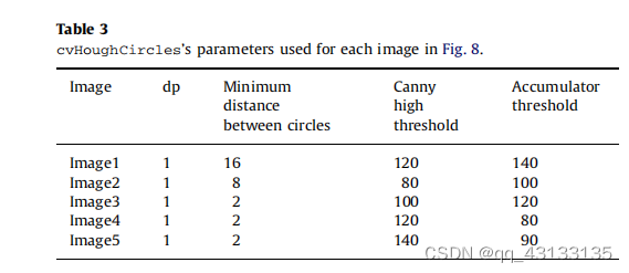
chart 8 The fifth column in is OpenCV be based on CHT Circle detection algorithm cvHoughCircles Circle detected . The reason for choosing OpenCV[66] Compare , Because OpenCV Realized eneric Image processing and computer vision algorithms are the fastest in the literature , And it's widely used , and OpenCV It's open source. , Anyone can repeat the same result . We noticed that cvHoughCircles There are many parameters ( Similar to many other circle detection algorithms in the literature ), Each image must be provided in advance by the user . In order to obtain cvHoughCircles Result , We use s¼1:0 Of 5 x 5 Gaussian kernel smoothing image . Then we tried many different parameters , And in the picture 8 The best results are presented in . surface 3 Lists the methods used to get cvHoughCircles The parameters of the result , Pictured 8 Shown . From the table 3 It can be noted that ,cvHoughCircles You need a different set of parameters to get the best results for each image . Because there is only one set of default parameters ,cvHoughCircles Or many valid circles cannot be detected , Or produce more error detection , This is not shown in this article .
From the picture 8 It can be seen that ,EDCircles Most effective circles are detected in real time , and cvHoughCircles Not only can not detect many effective circles , There will also be a lot of error detection . This is in Imagel It's more obvious in the middle ,cvHoughcircles Execution time is close to 1 second , Output 71 A circle , Many of them are false detections . Let's stress again ,EDCircles It has no parameters , in other words , It uses the same internal parameters for all images ; However , Use cvHoughcircles Get the best results , The user must provide a different set of parameters for each image by trial and error .
chart 8 The last line in the Image5 Special attention required , This is one from Sweedish traffic sign Circular traffic signs in the database [67]. Because of the camera's perspective , This circular sign is displayed as an ellipse instead of a circle . From the picture 8 Can be seen in ,EDCircles This elliptical circle is correctly detected ; However , Traditional ring detector , Such as cvHoughcircles, Three different rings can be detected , But none of them can correctly represent traffic signs .
surface 2 Pair graph 8 Of each image in the EDCircles The running time is analyzed , And with cvHoughcircles The running time is compared . obviously , For typical 640 x 480 Camera input size ,EDCircles It runs in real time ,EDPF Most of the time is spent on edge segmentation detection , Not circle detection and verification . Also pay attention to ,EDCircles Than cvHoughcircles fast 14 times , This may be classic CHT The fastest implementation of the algorithm .
Next , We will EDCircles And [26] For the first time 、 Recently [27,28] Improved random circle detection in (RCD) Algorithm comparison , In this algorithm , The author discusses different RCD variant , And it is named GRCD-R The result of the variant of . Unfortunately , This algorithm has no public implementation . therefore , We extract test images and their results from the author's original paper [28], Input the test image EDCircles And compare the results .
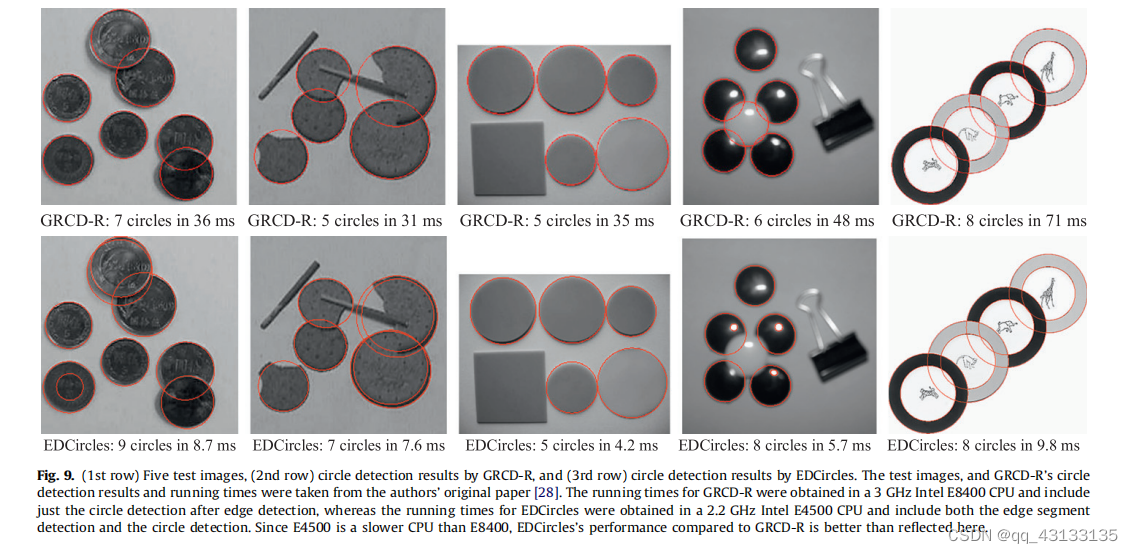
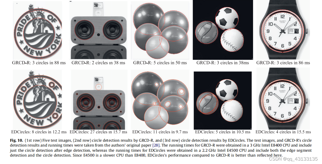
chart 9 Sum graph 10 Respectively [28] Acquired 10 Test images and GRCD-R Generated results , as well as EDCircles Generated results .Chung They point out that ,GRCD-R The running time of the result is 3 GHz Intel E8400 CPU[28] I got it on . For a fair comparison GRCD-R and EDCircles Running time of , We are 2.2 GHz Of Intel E4500 CPU Up operation EDCircles, This is also a similar E8400 Of Core 2 Dual core CPU, But according to CPU The benchmark , Its clock speed is slow ,CPU Lower rating .
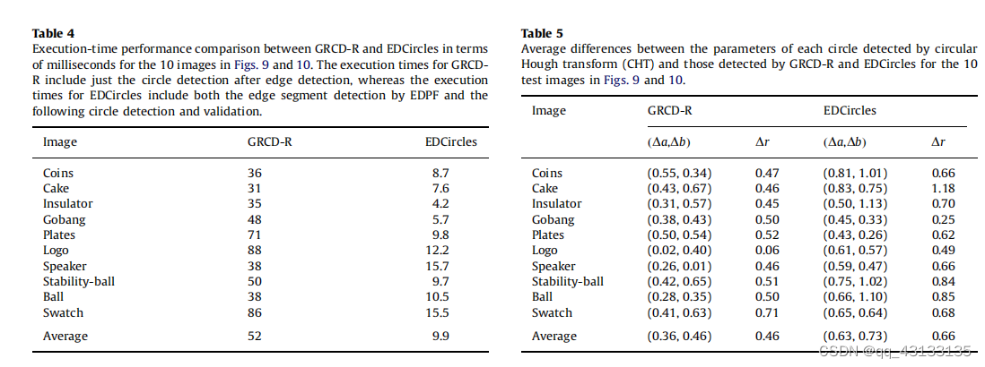
From the picture 9 Sum graph 10 The result can be clearly seen ,EDCircles stay “ gobang ” and “ gobang ” In addition to some light reflection , Most valid circles are detected “ Stabilization ball ” Images and “ gobang ” The center ball of the image , Average running speed ratio GRCD-R fast 5 times . chart 9 Sum graph 10 Of 10 A picture ,GRCD-R and EDCircles The comparison of execution time is shown in table 4. It should be noted that ,GRCD-R The execution time of only includes circle detection after edge detection , and EDCircles The execution time of includes EDPF Edge detection based on , It also includes the following circle detection and verification . in consideration of EDCircles At least half of the running time is spent on edge segment detection , also EDCircles Run on slower CPU On , therefore EDCircles Actual performance ratio GRCD-R Better than watch 4 Reflected performance .
The other thing to note is that ,EDCircles It can detect circles of various sizes in the image , and GRCD-R Many valid circles cannot be detected . This is in the picture 10 Of “logo” and “speaker” It is more obvious in the image ,GRCD-R Only large circles are detected , and EDCircles Many circles with large or small radii are detected .
EDCircles One disadvantage of the method is to detect multiple circles around fuzzy circles . This is in the picture 9 Of “ COINS ” and “ The cake ” It is more obvious in the image ,EDCircles Two circles are detected surrounding two different coins , Two circles surround three different circular objects . Please note that , There are shadows around the boundaries of these objects , These shadows are EDPF detected , And be edcircle Into a circle .GRCD-R The reason why multiple circles around the same object are not detected may be GRCD-R The edge graph used is relatively clean , These shadows are not used as edges . Because we don't know GRCD-R The edge graph used to calculate the circle , So we can't be right in this sense GRCD-R and EDCircles Make a fair comparison .
In order to evaluate EDCircles The accuracy of the , We have a picture of 9 Sum graph 10 Shown 10 The traditional circular Hough transform is applied to test images (CHT)[12] operation , Get the ground truth result . In order to make CHT The results are as accurate as possible , We will use abscissa 、 The granularity of ordinate and radius is set to the accuracy of one pixel . surface 5 Shows... In each test image ,CHT Each circle parameter detected is related to GRCD-R and EDCircles The average difference of each circle parameter detected . It can be seen from the results ,EDCircles Although there is no GRCD-R So precise , But the accuracy is sub-pixel .
In the next experiment , We measured edcircle Performance in detecting near circular elliptical objects . As we pointed out earlier , According to the perspective of the camera , Circular objects may appear slightly oval in the image . A good circular detector should be able to handle this situation .
chart 11 It shows EDCircles Performance of detecting near circular elliptical objects in four images . Two of these images are from the pupil detection application ; The other two are from the Swedish traffic sign database [67], Contains several circular traffic signs . Please note that , All round objects , Because of the camera's perspective , It looks slightly elliptical in the image , No error detection has been detected . What we want to emphasize is ,EDCircles It is not a general ellipse detection algorithm , I'm not going to be a . contrary ,EDCircles Try to detect circular objects that look slightly elliptical due to the camera's angle of view .
Informally , We can say EDCircles Try to detect ellipses whose major axis is not more than twice the minor axis . This is due to the 2.5 The arc connection heuristic algorithm described in section , The algorithm only works when the difference of arc radius is no more than 50% Connect the two arcs together . If a circular object appears too elliptical due to the camera's angle of view ,EDCircles It will not be detected .EDCircles Website [55] Most of the arbitrary ellipse detection shown on is because the entire boundary of the ellipse is detected as a single closed edge segment .
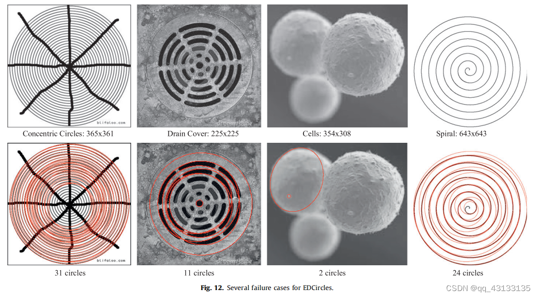
chart 12 Analysis of the edcircle Several failure cases . The first column shows a group of closely concentric circles , It is divided into eight parts , This triggered EDCircles Arc connection heuristic . It can be seen from the results , In some cases ,EDCircles Incorrectly connect the arcs of the outer circle and the inner circle , Resulting in half of the outer circle and half of the inner circle . This is related to edcircles Greedy to use join Heuristics are relevant . Think about it 2.4 section , When EDCircles When trying to expand an arc , It will generate a set of candidate arcs , And connect the current extended arc with the candidate arc closest to the endpoint . If the connection is successful , Then connect the arc immediately , And the connected arc will not be separated in the future . This is a greedy heuristic , It was chosen for performance . Although this heuristic method can detect circles well in many cases , But when concentric circles are divided into two or more areas , It will fail , Pictured 12 Shown . stay “ Sewer cover ” Similar problems can be observed in natural images of ,EDCircles Again, connect the arc from the outer circle with the arc from the inner circle . chart 12 The images in the first and second columns illustrate EDCircles Another weakness of ; Failure to detect small split circles . Please note that , In these two images ,EDCirdes No small circle in the center of the image is detected . This is related to EDCircle Arc generation strategy of . To recall 2.3 section , At least three lines of the generated arc turn in the same direction , And meet the angle constraint , Generally, it is not satisfied in a small circle , Detection failed . chart 12 The third column of shows three blood cells with blurred boundaries , The test either fails , Or produce imperfect results . When the boundary of the object is fuzzy ,edcircle Edge segmentation detector used EDPF Rough edge segmentation will occur , Cannot convert to arc , Detection failed . chart 12 The last column of shows a spiral and EDPF Detected circles . When the spiral rotates ,EDCircles There will be many arcs , These arcs are combined to form the circle shown in the figure . Once again, we see that the arc of the inner circle and the arc of the outer circle are connected . Because the verification of Helmholtz principle can not eliminate these wrong detection .
Our last experiment is measurement EDCircles Performance in noisy images . So , We get an image containing several small circles and large circles , Add different levels of Gaussian white noise to the image , And provide the image to EDCircles.
chart 13 It is shown on the sample image containing a large circle and several small circles , With the increase of Gaussian white noise volume ,EDCircles Performance of . Be careful , As the noise increases , The detection of small circles begins to fail ;
until σ = 60 Gaussian noise , Only big circles are detected . Increasing the noise will cause the detection to fail completely , As shown in the figure . The reason why the detection failed is , As the noise increases , The boundary of the circle is approached by many short edge segments , Instead of a few long edge segments in the image with less noise . This means that the arc that approximates the circular boundary will be short , Cannot be connected , To make up for the circle . Please note that , There is no error detection in all images , This is also very important . We also observed that , In noisy images ,edcircle The running time of will increase . The reason is that edge segmentation detection is added
from EDPF Time . As the amount of noise in the image increases ,EDPF It takes more time to calculate the edge segment , Because many pixels are beginning to become potential edge elements . Circle detection after edge detection remains fairly stable in all images .
chart 14 It shows the analysis of noisy images at different scales ( contain σ = 100 Gaussian noise of ) Result . At full scale , No structure detected , Although they are visible to human observers . This is because the human visual system has carried out multi-scale analysis , It can detect structures in strong noise . Run at half and quarter resolution edcircle, We can see that several circles are detected now . We come to the conclusion that : When there is strong noise , Denoising or amplification steps help EDCircles Many valid circles are detected .
4. Conclusion
EDCircles It's a real-time 、 Nonparametric circle detection algorithm , It is through our nonparametric edge segmentation detector (EDPF) The detected edge is post processed .EDCircles First, put each edge segment ( A continuous chain of pixels ) Convert to a group of line segments . Then convert the line segment into an arc , Two heuristic algorithms are used to connect them into candidate circles and near circular ellipses . In the last step , Use Helmholtz principle to verify all candidate circles , Thus eliminating error detection , Only valid circle detection is left . The experiment shown in this paper ( And readers may wish to http://ceng.anadolu.edu Other experiments performed online ).tr/CV/EDCircles/Demo.aspx) The test results show that ,EDCircles It has a high detection rate , Good accuracy , Fast running speed , Only a small amount of error detection or no error detection . We hope edcircle It can be widely used in product inspection in real-time automation tasks such as automation , Pupil detection , Circular traffic sign detection , And similar applications .
thank
We are very grateful to anonymous reviewers for their profound comments , This greatly helps the development of this article . We also thank the Turkish scientific and Technological Research Council (TUBITAK) Support for this work .111 e053.
reference
[1]…
边栏推荐
- BUUCTF刷题笔记——[极客大挑战 2019]EasySQL 1
- Precautions for single chip microcomputer anti reverse connection circuit
- 下一个行业风口:NFT 数字藏品,是机遇还是泡沫?
- 出现Permission denied的解决办法(750权限谨慎使用)
- Daily question brushing plan-2-13 fingertip life
- Tidb ecological tools (backup, migration, import / export) collation
- Explore pointers and pointer types in depth
- The real machine cannot access the shooting range of the virtual machine, and the real machine cannot Ping the virtual machine
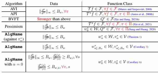
- Princeton University, Peking University & UIUC | offline reinforcement learning with realizability and single strategy concentration
- codeforces每日5題(均1700)-第六天
猜你喜欢
How to do function test well
Princeton University, Peking University & UIUC | offline reinforcement learning with realizability and single strategy concentration
【RISC-V】外部中断

Sign SSL certificate as Ca

Pytorch基础——(1)张量(tensor)的初始化
暑期刷题-Day3

JS音乐在线播放插件vsPlayAudio.js

Performance test method of bank core business system

Performance analysis of user login TPS low and CPU full

codeforces每日5题(均1700)-第六天
随机推荐
pytorch加载数据
JS音乐在线播放插件vsPlayAudio.js
Tidb ecological tools (backup, migration, import / export) collation
如何做好功能测试
February 14, 2022 Daily: Google long article summarizes the experience of building four generations of TPU
codeforces每日5題(均1700)-第六天
Redis cache breakdown, cache penetration, cache avalanche
数据分析——seaborn可视化(笔记自用)
Linear programming matlab
three.js网页背景动画液态js特效
Shell 传递参数
Item 10: Prefer scoped enums to unscoped enums.
ASU & OSU | model based regularized off-line meta reinforcement learning
These are not very good
Software design principles
IPv6 comprehensive experiment
蓝色样式商城网站页脚代码
Remote Sensing Image Super-resolution and Object Detection: Benchmark and State of the Art
指针笔试题~走近大厂
Cross origin cross domain request

