当前位置:网站首页>How to make a cool ink screen electronic clock?
How to make a cool ink screen electronic clock?
2022-07-05 01:49:00 【Chip home】
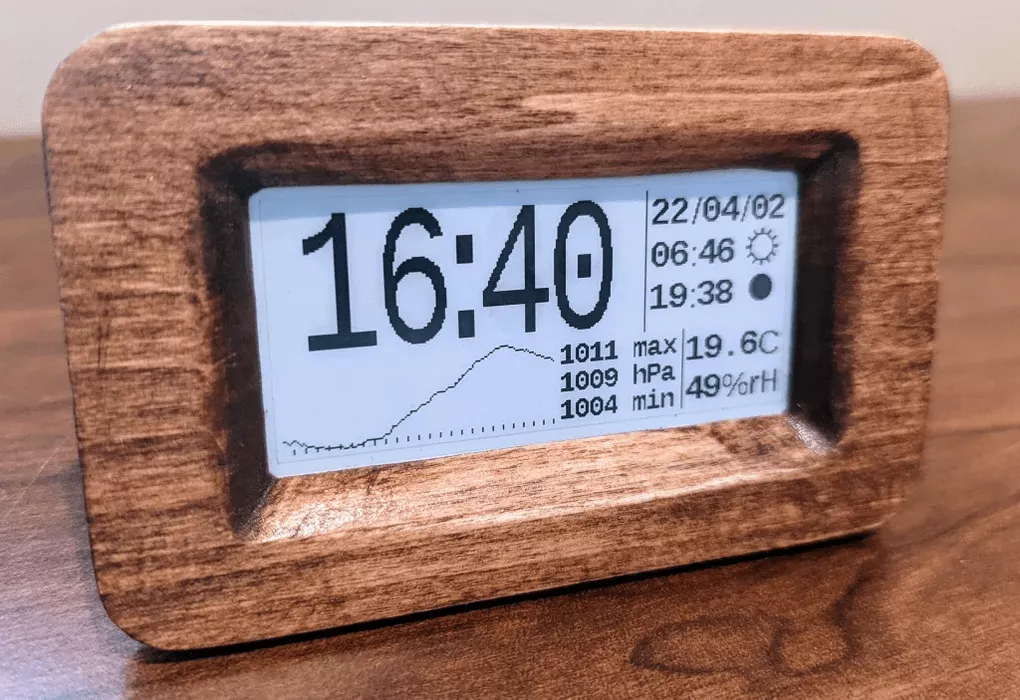
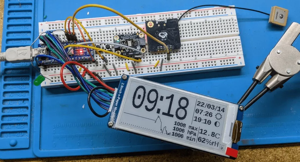
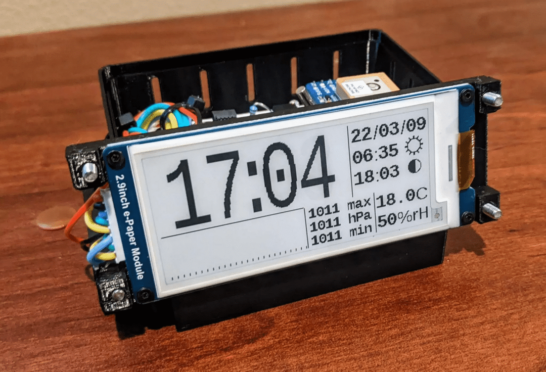
This week I will introduce to you a beautiful ink screen electronic clock , It has the function of meteorological station ( Can pass GPS Automatic setting ), use 4 section AAA Battery life 6 About a month or so , and , To ensure safety and reliability , It doesn't require any network connection .
Features include :
Automatic setting ( adopt GPS)
Current temperature .
The current humidity .
Show past 25 Pressure chart of the pressure within hours .
Sunrise and sunset time
The current phase of the moon
stay 12 Hours or 24 Select between hour modes .
Choose between English and metric units .
This project has two different versions , Namely “ Simple and easy ” edition and “ Low power ” edition .
“ Simple and easy ” edition Is based on Arduino Nano Of . The aim of this version is to minimize the cost 、 The number of parts and the complexity of fabrication ; The downside is that you need to use a USB 5V Adapter to power the clock .
“ Low power ” edition Use one 32k The oscillator , Maintain accurate timing with minimal power . This oscillator allows the clock to run on batteries .
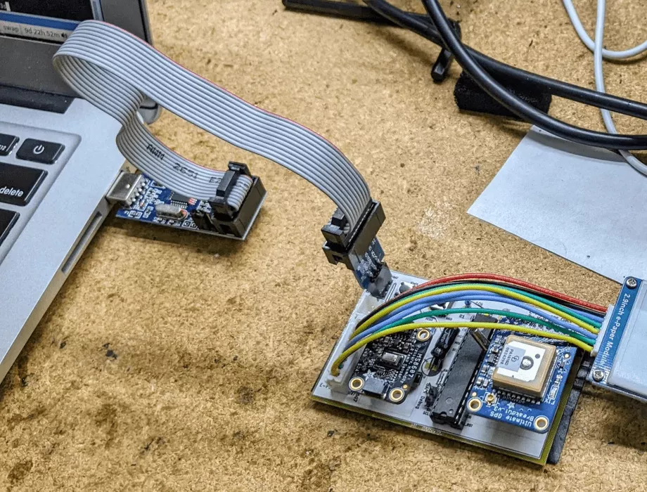
The first 1 Step :" Simple and easy " Revision parts list
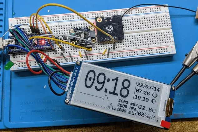
Arduino Nano
Waveshare 2.9 in EPaper modular
Adafruit MS8607 pressure / humidity / Temperature sensor
Anything with a 9600 Baud TX Of GPS modular
Circuit board ( It can be a prototype board or a piece for CNC Copper plate )
Several button switches ( To change UTC Time offset and display preferences )
The material used to make the shell ( At the end of the article, there will be
.3mf、.scadand.dxffile )USB Charger and charging cable
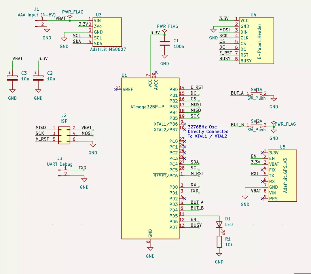
The first 2 Step :" Low power " edition
These materials are the same as the simple version above :
Waveshare 2.9 in EPaper Module
Adafruit MS8607 pressure / humidity / Temperature sensor
Circuit board
Several button switches
The material used to make the shell
Besides , You also need to :
Atmega328P DIP edition ( You can also choose SMD Packaged version , But in 32K It will be more difficult to weld on the crystal )
32768 Hz Crystal ( This oscillator is the key to low power design )
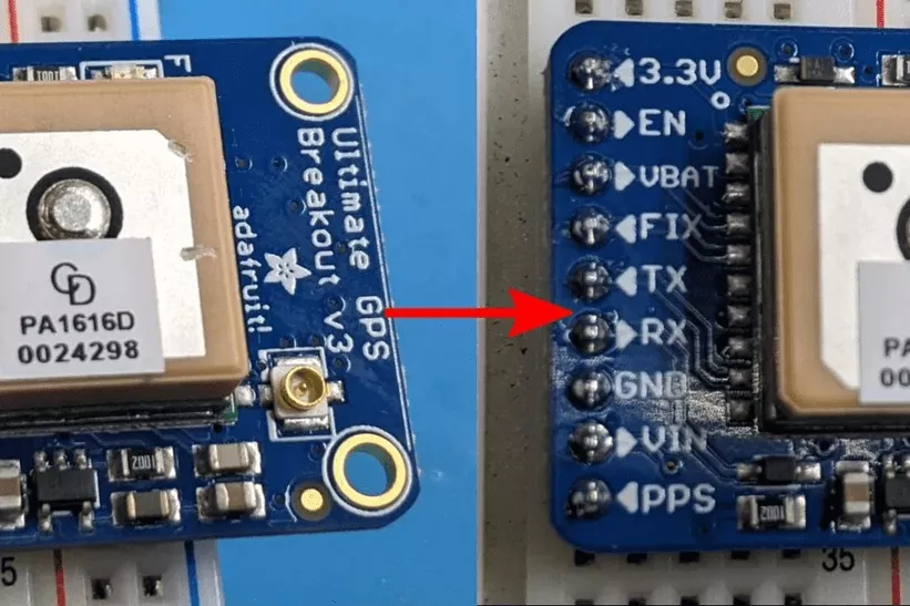
Adafruit GPS modular ( This module is better than " Simple and easy " The quality of modules in the version should be higher , Because it can track more satellites ( To lock faster ), Provide an enable pin ( For low power consumption ) And a port to keep its memory active ( For quick re locking ). If all these features are not worth the cost to you , You can add your own enablers FET, Magic changes a cheaper module to complete this work . How to do this will be explained later )
LED+ resistance ( Naked Atmega328P There's no way to tell you if it's working , Flashing lights can provide a 1ms/ Of a second " heartbeat ", Almost no power consumption , But it provides useful feedback )
How many? 10uF and 100nF To smooth the supply voltage
The battery ( I use it 4 individual AAA The battery , But anything that can be obtained 5-7 A battery with a voltage of 25 volts can be used )
( Optional ) One is used to pass through ICSP To program a chip 3x2 syringe needle ( If you can remove Atmega328P reprogramming , Then you can skip this connector )
( Optional ) One for the UART Debugging 1x2 Pin connector ( This is only required if the board is unstable )
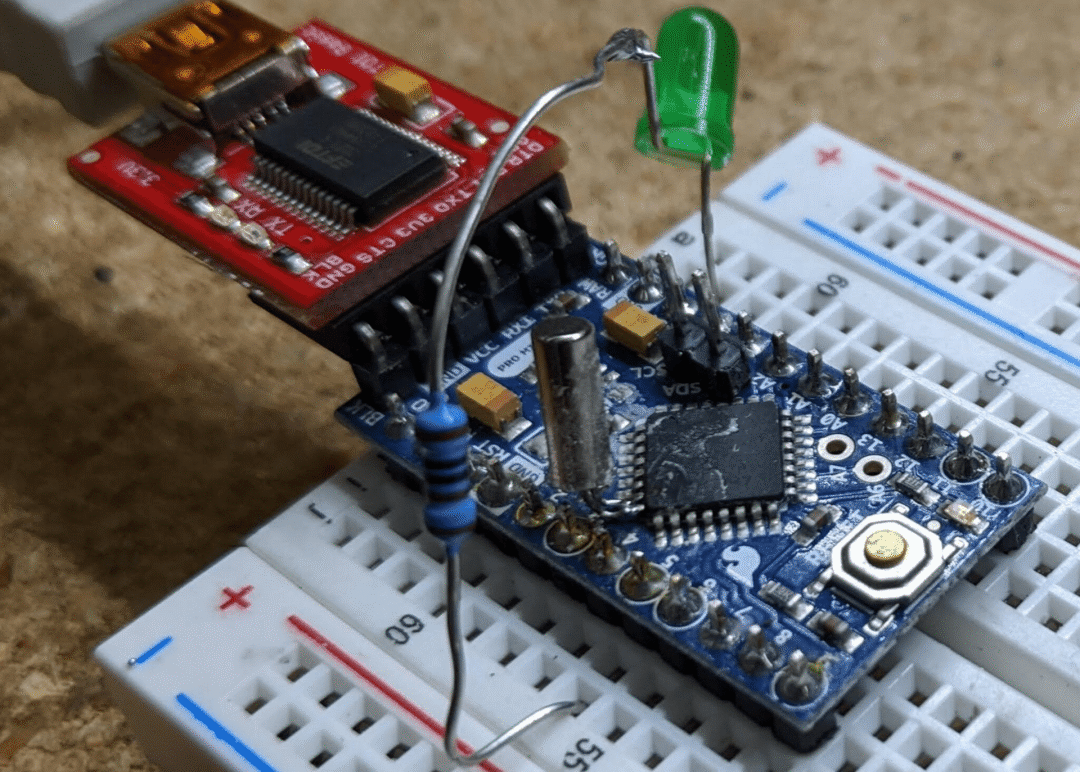
The first 3 Step :Arduino Mini edition
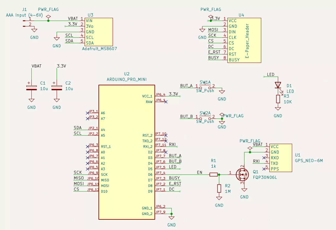
As mentioned above, there are two versions , This is an extra version , The reason why there is such an extra version , It is because we are now in " Shortage of parts ", image Atmega328P Such chips will be out of stock for a long time .
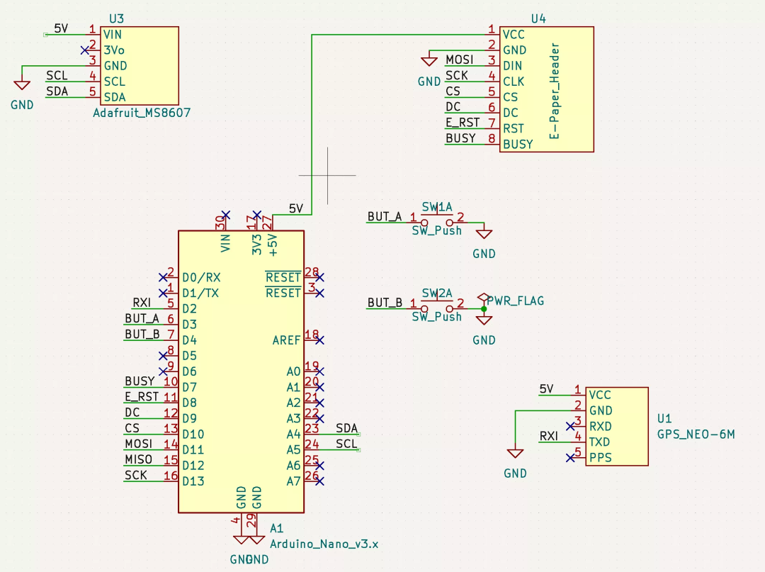
You can use it. " Simple " Version of the firmware runs this version , perhaps , If you have confidence in your welding skills , You can weld one on the microcontroller 32k The crystal of ( As shown in the figure above ), And use 32k Version of the firmware ( See the next section for more details ).
The above schematic diagram uses a " cheap GPS " Solutions to connect , But if you use something else ( such as Adafruit) In the schematic diagram GPS part , You can also use other ( such as Adafruit Of )GPS( As shown in the schematic diagram of the previous step ).
The first 4 Step : cheap GPS( Optional )
With competitors (12 dollar ) comparison ,Adafruit Of GPS The device is very expensive (30 dollar ). If you think the added features ( It is described in the section of low power components ) No " Worth ", You can put anything you can with 9600 Baud transmission NMEA A string of GPS Throw the module in ( Most of the GPS All modules are OK ).
But now there is a new problem to be solved : Most of these units lack an enable / Disable pin , and GPS The unit usually consumes 30-100 Milliamperes of electricity . We can use one N-MOSFET( Or similar ) Black out a disable switch . The schematic diagram above shows the basic idea . We can also do that falstad[1] Try to .
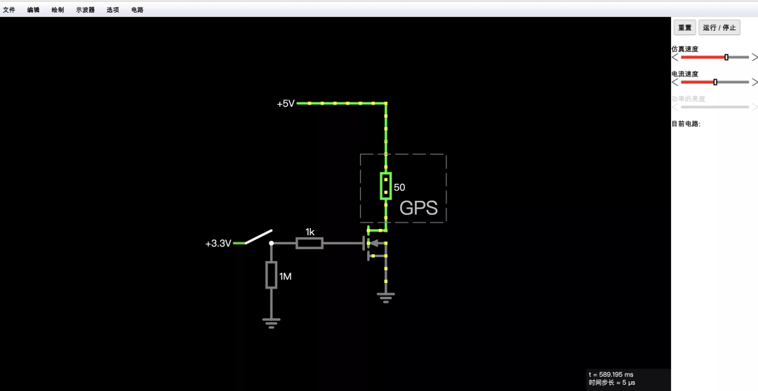
This power switch circuit has a trade-off . If you are interested in more details , Please see Appendix B.
The first 5 Step : Low power hardware modification
If you are making " Simple and easy " edition , You don't need to read this part . about “ Low power ” edition , These modifications will greatly improve battery life .
To illustrate , We will assume that the power supply comes from a set of AAA The battery , Can provide 1000 mah . Let's assume that you are using 32K Of Adafruit edition , And no changes have been made . The following is an example of power decomposition .
" sleep / close " CPU、GPS、MS8607 and EPaper: The measured value is 30-70uA( We think it's 50uA).
Screen update :5 Ma , Every minute 2 Seconds at a time :
5 * 2 / 60 = 166 uAGPS to update : Once a day , Every time 50 Ma , Every time 10 second .
50 * 10 / 86400 = 6 uAMS8607 LED:100 uA
Adafruit GPS Pull up resistance :500 uA
therefore , We have (50 + 166 + 6 + 100 + 500)= 822 uA Average current consumption , It's about 50 Days of power .
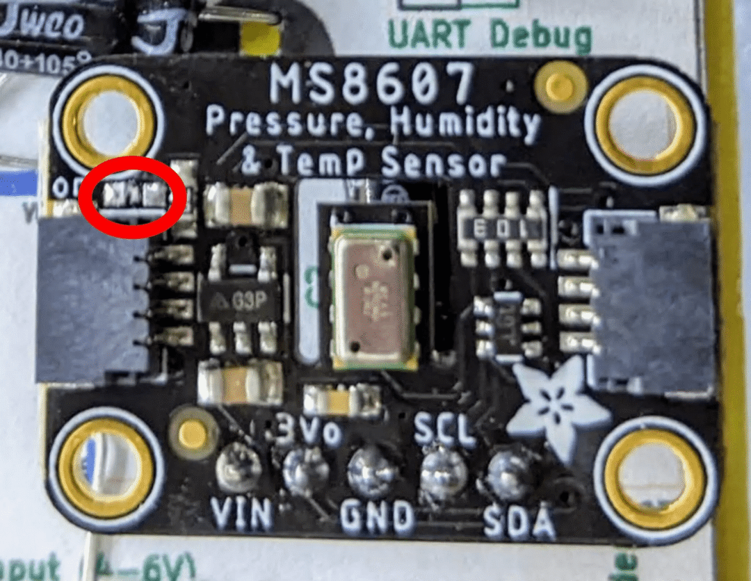
If you remove MS8607 LED and GPS Pull up resistance , Our electricity consumption will be reduced to 222 uA, That is about 187 Days of electricity consumption , It greatly increases the use time .
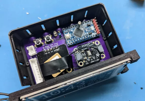
1、 First , Recommend from MS8607 Remove LED( The details are shown in the figure above )
2、Adafruit GPS The pull-up resistance on the is caused by Adafruit Added by the designer of , bring EN The pin becomes an option . But it also has a disadvantage , When you pull it to the ground ( Ban GPS) when , There are about 500uA The current of is consumed in the pull-up resistor . Since the enabling pin of this design is actively driven , You can remove this resistor ( The details are shown in the figure above )
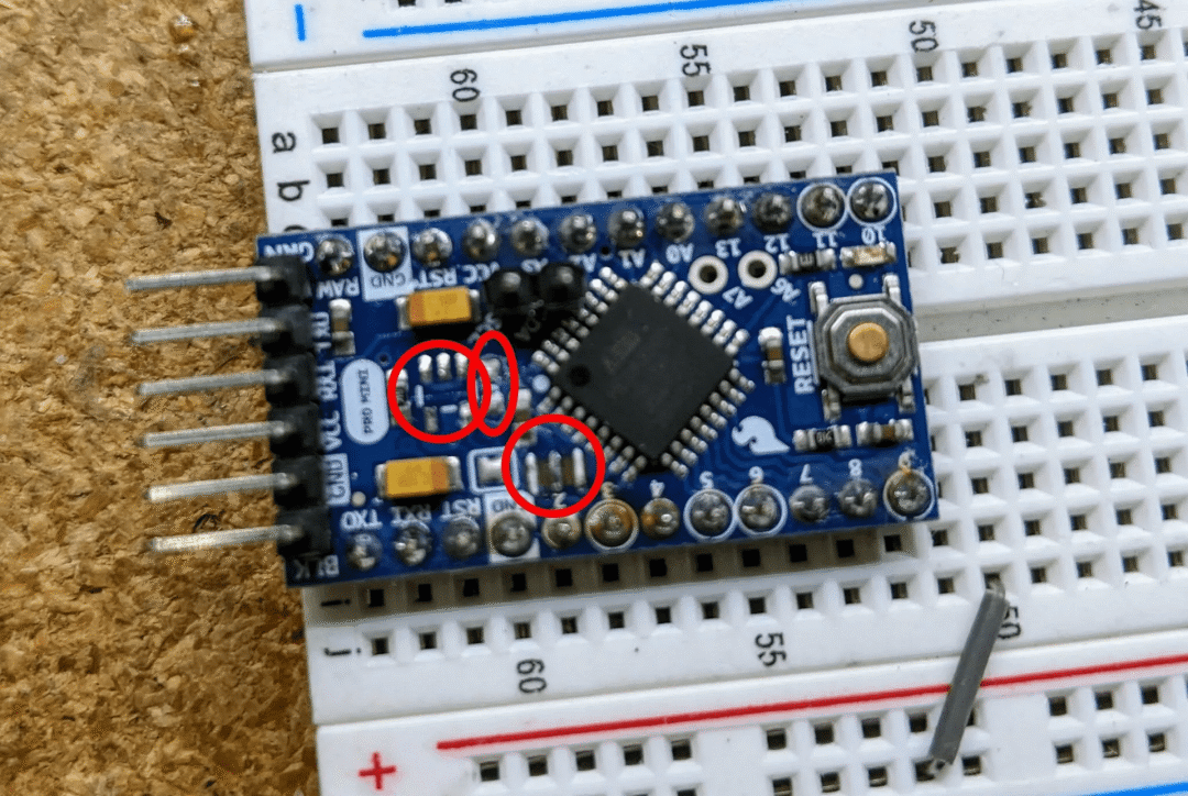
3、 Professional Mini modification . Search engine search "Arduino mini low power consumption " Learn more , Basically , You will want to remove the voltage regulator and LED, To reduce power usage . We switch to MS8607 Voltage regulator of (3.3V, Lost in idle time 35-55uA Power ) by pro mini Power supply .
4、 stay pro mini In the picture of , I also removed the crystal oscillator , by 32K The chip of the crystal is ready . Only in 32K In the case of the crystal version, this crystal is removed , And only on pro mini The inner fuse of the is reprogrammed and then removed , It will be explained later .
The first 6 Step : The firmware
In this step , I have attached nano and 32k Crystal version .hex file ( Both versions apply to pro-mini, If you're not sure which version to use , Just use nano edition ).
If you want to build your own / Modify the source code , You can visit GitHub:https://github.com/mattwach/epaper_clock
Build yourself .hex Firmware file ( Optional )
Be careful , This code does not use Arduino library , Because the generated code is too large , Cannot be in Atmega328P Installation on ( And this is my personal preference ). It is to use C language-written , Used Arduino[2] Also used AVR Base library as the base . If you want to compile code , You need to install ( Free of charge )avr-gcc Tools [3], clone epaper project [4] Source code . Then enter firmware/[5] Directory and enter .
makeIf the code establishes , Can open Makefile[6], Look at these options .
# This is the Low-power stand alone chip configuration.
CLOCK_MODE ?= USE_32K_CRYSTAL
UART_MODE ?= HARDWARE_UART
F_CPU ?= 8000000

# This is the easy-to-build firmware that is based on an Ardino Nano
#CLOCK_MODE ?= USE_CPU_CRYSTAL
#UART_MODE ?= SOFTWARE_UART
#F_CPU ?= 16000000
If you're building 32k Crystal firmware , The configuration is correct . If you build nano Version of , You need notes 32k Period , uncomment nano That code , Then again, make.
There is also a special debugging mode , Through hardware UART With 9600 Baud's speed dump log information . You can now ignore , But remember it , Because it may be useful in the future .
# Uncomment to activate debug via the UART TX (9600 baud)
#DEBUG_CFLAG := -DDEBUG
Last , You can decide by changing several variables GPS How long should it be activated . Run once a day by default , But if GPS It takes a long time to lock , It will reduce the operating frequency , So as to reduce battery consumption . Please be there. src/gps.c[7] Read all relevant content in .
This part of the file can be downloaded at the end of the text !
The first 7 Step : Use ICSP Upload firmware
This section is for those who upload code to a standalone Atmega328P The little partner of the chip prepared , If you want to upload to Arduino Nano, Please skip to the next step .
You need one ISP( or ICSP) The programmer . You can use a spare one Aruino Uno/Nano Make one of your own . You can search in search engines "Arduino ISP Programmer" Please note that , Many of these guidelines assume that your real goal is to install a bootstrap , But for us , No bootstrap required , Because we will use ICSP Upload .hex file .
Power off detection
In my Atmega328P On , Power off detection is set to 3.5V( It looks like an old version ), So I use this command to disable power-off detection .
/usr/bin/avrdude -patmega328p -cusbasp -Uefuse:w:0xFF:mYour may be different , It depends on your “ISP programmer”(-c Options ). It's also possible that you don't need to set , Just in case .
The first 8 Step : Use Avrdude
We can use one called avrdude Free tools , To upload the hex file it created to your Uno/Nano/. We can also download and use directly from the command line avrdude.
use Arduino IDE Run an upload with the output record open ( Light up demo Or something demo), Then copy the commands it uses . perhaps
Read the official avrdude file [8] perhaps
Read reference online to use avrdude A tutorial for
This is where I am nano Used in version avrdude command ( adopt make Upload ).
For reference :
/usr/bin/avrdude \
  -v \
  -patmega328p \
  -carduino \
  -P/dev/ttyUSB0 \
  -b57600 \
  -D \
  -Uflash:w:epaper_firmware_using_arduino_nano.hex:i
This is me in ISP Used in version :
/usr/bin/avrdude \
  -v \
  -patmega328p \
  -cusbasp \
  -Uflash:w:epaper_firmware_using_32k_crystal.hex:i
What we use here is Linux.Mac and Windows And it works , But like -P Such options will be different ( That is to say Windows It could be -PCOM1).
Again , This part of the document can be found in Download at the end of the article !
The first 9 Step :32K Crystal oscillator
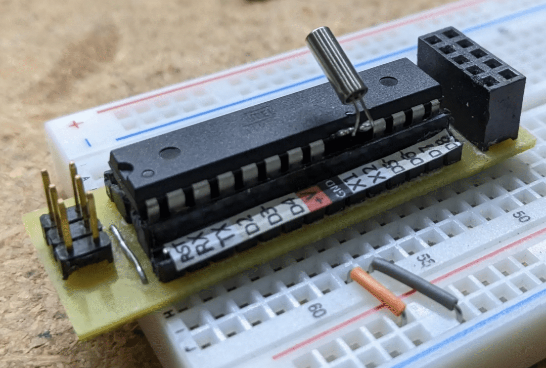
If you are making " Simple and easy " edition , Please skip this step . If you're using 32k Crystal firmware , You need to install crystals to make the firmware work .
First (!) You also need to configure ATMega328P Internal fuse of , To use internal 8Mhz Crystal .
It's important to do this first , because 32K The crystal will replace any existing crystal . If you don't change these fuses , The chip will become unresponsive , Until you reconnect one 8 or 16Mhz The oscillator .
as far as I am concerned ,Arduino pro mini Also needed ISP To change the inner fuse ( But I could be wrong ). I looked it up "Arduino ISP", To get the correct pin mapping , So that ISP Connection between connector and bread board ( As shown in the figure above ).
Connected to my ISP programmer after , You can use this command to check the current internal fuse configuration .
$ avrdude -patmega328p -cusbasp
...
avrdude: safemode: Fuses OK (E:FF, H:DE, L:E2)
L:E2 It's the interior we want 8mhz Set up . If your values are different , You can update it with a command like this .
/usr/bin/avrdude -patmega328p -cusbasp -Ulfuse:w:0xE2:mAnd then check again .
After the internal fuse is set , You can weld the crystal . It is recommended to connect the crystal directly to the microcontroller pin , To reduce stray capacitance . Too much capacitance will make the crystal take longer to start oscillation ( Or failed to start ).
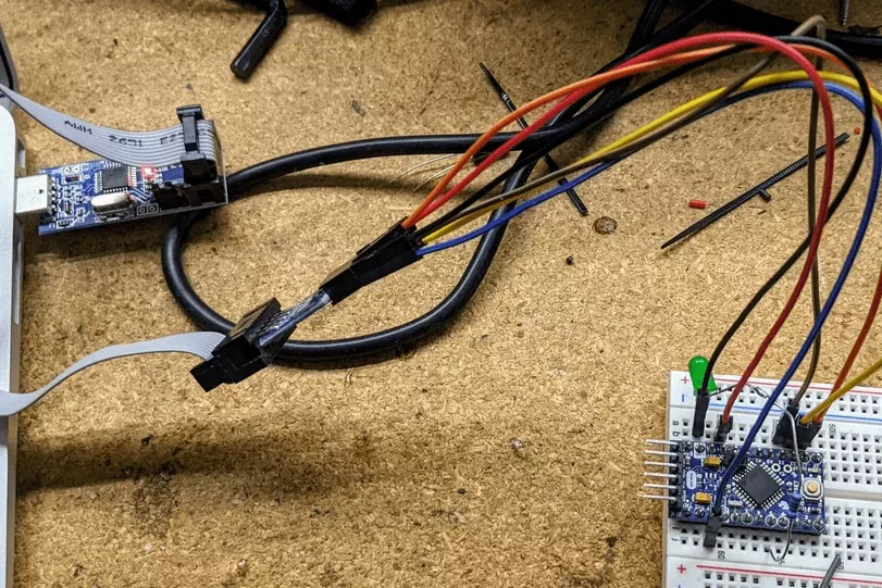
The first 10 Step :( Optional ) The first step
Refer to step 1、 step 2 Or steps 3 The design schematic you selected in .
You can verify the situation so far on the bread board , Just put one LED/Resistor from D5 Connect to the ground , Then upload the firmware . If everything goes well ,LED Will flash briefly once per second ;
Next , You can add EPaper display . The data on the monitor will not be correct , But it should show some data ;
then , add to PHT modular , And verify that it works ;
And finally GPS modular .
If the test is normal , We can move everything to a more “ permanent ” On the fixture of .
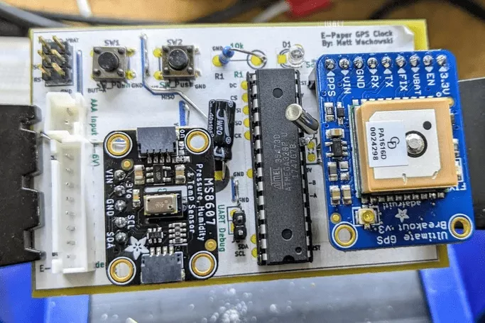
The first 11 Step : Circuit board assembly
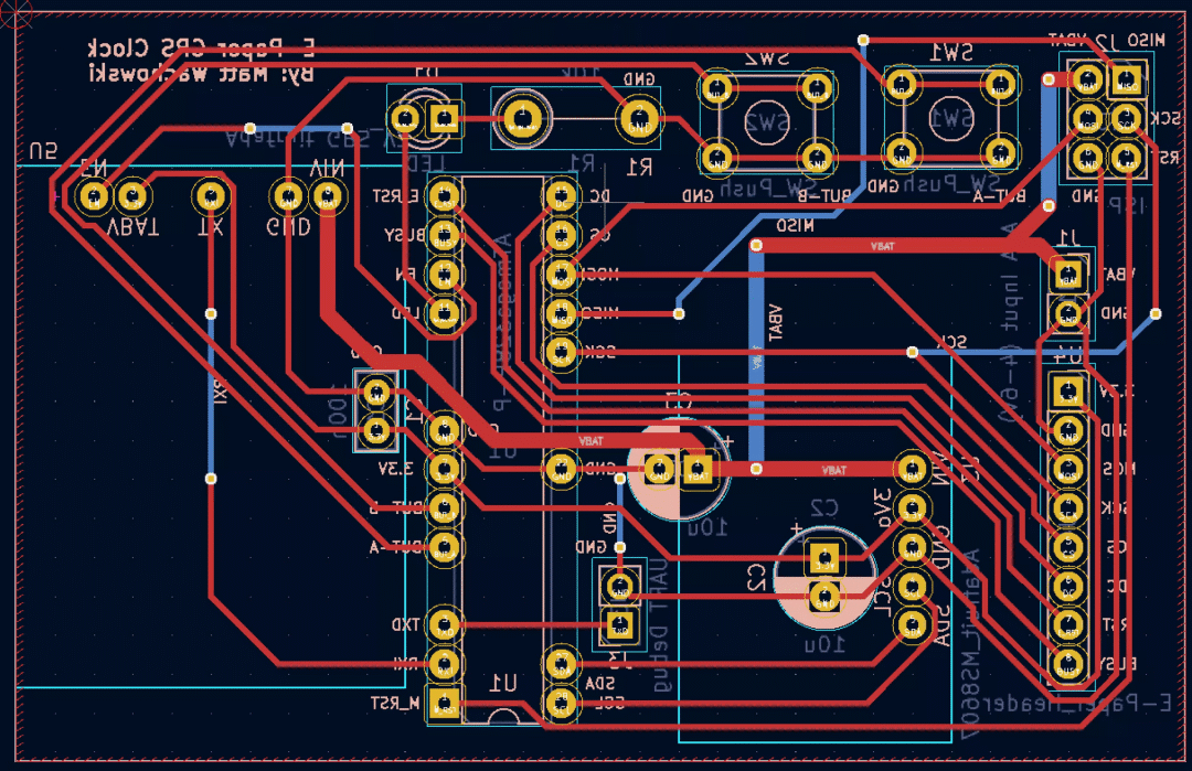
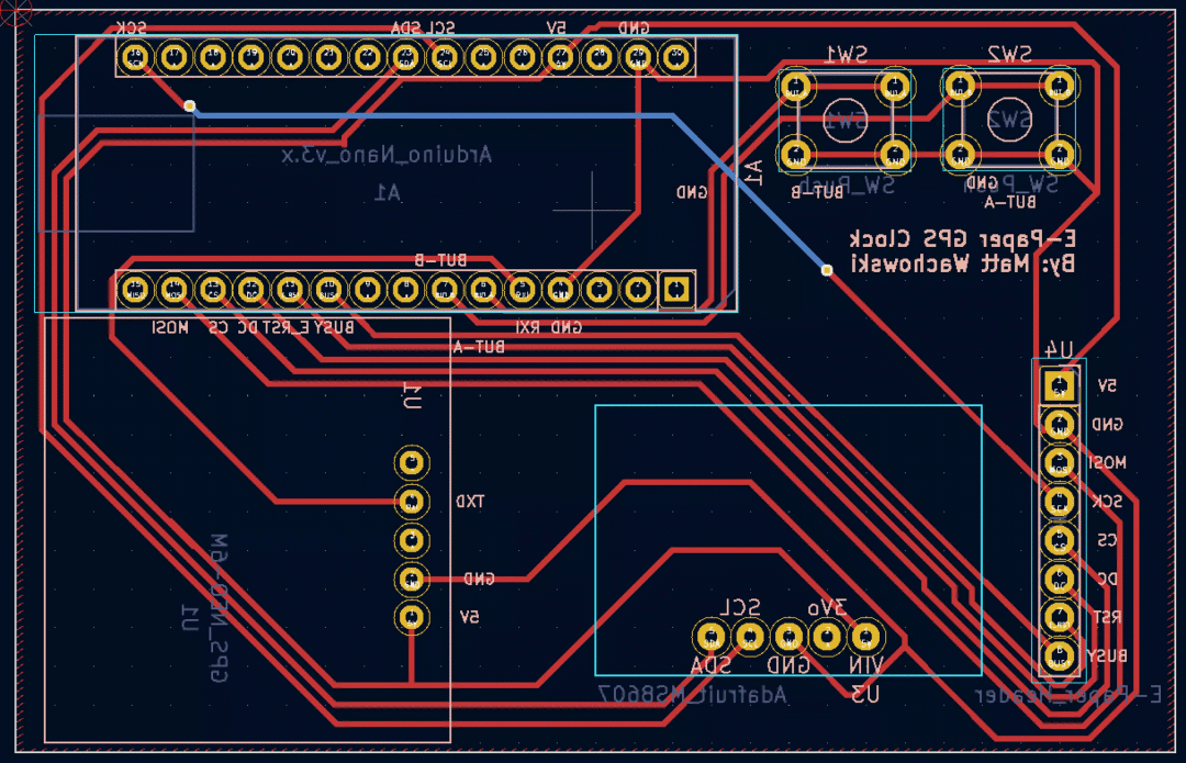
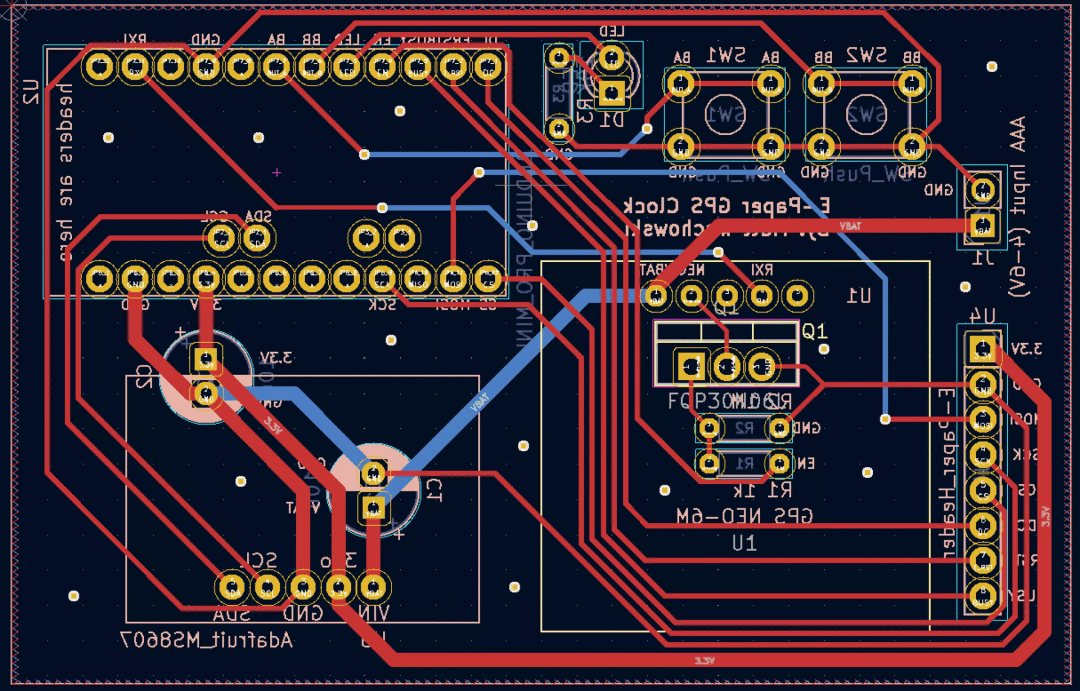
You can choose to use perf plate , use CNC Cut the board , Or send the design to the factory for manufacturing .
Kicad Design documents can be found in schematic/ Catalog [9] Find . There are three hardware options ( Are shown from the back , Because this is the way you wire by hand ).
I use my CNC Machine made ATMega328P edition . If you don't CNC Cut PCB And interested , You can try to search on the search engine "3018 PCB", You will find many videos and articles on this topic .
Gap setting 0.4 mm , But you can be narrower ( It may not be wider ). I use Flatcam take Kicad Of Gerber The output is converted to G Code .
Relevant documents can be found in Download at the end of the article To .
The first 12 Step : Case design
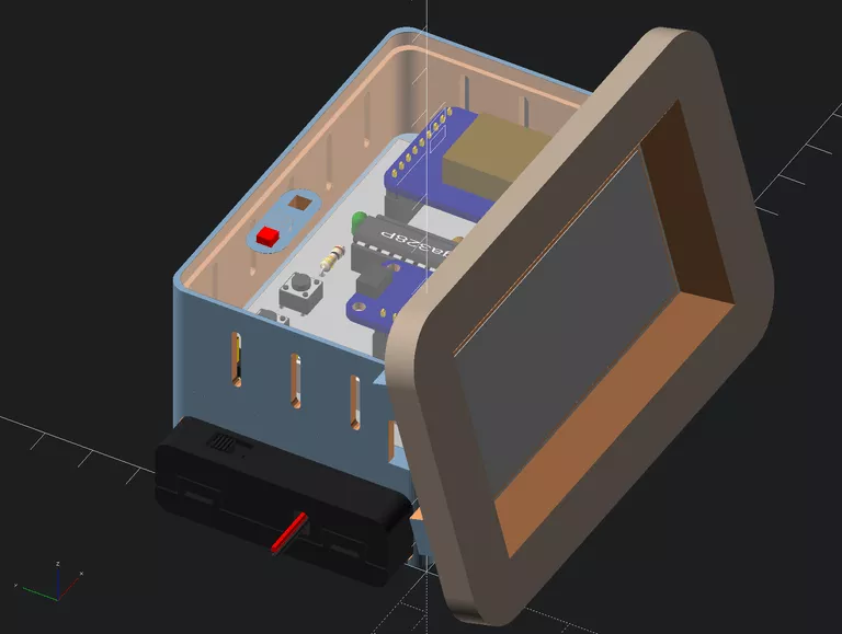


You can design any kind of look you want , We encourage you to be creative !
Here's how I made it ( All design documents can be found in Download at the end of the article To ).
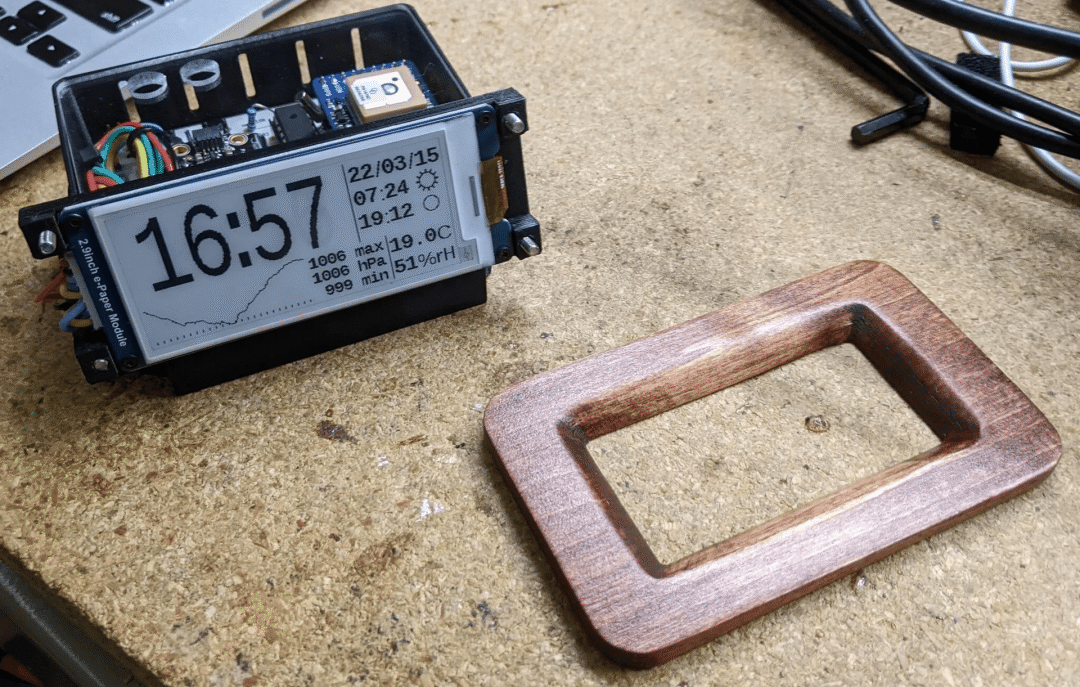
My design uses a 3D Printed support structure and two CNC parts : A top cover and front panel . CNC components are made of wood , Because I think it looks more beautiful than plastic . I am here OpenSCAD The whole thing is designed in advance .
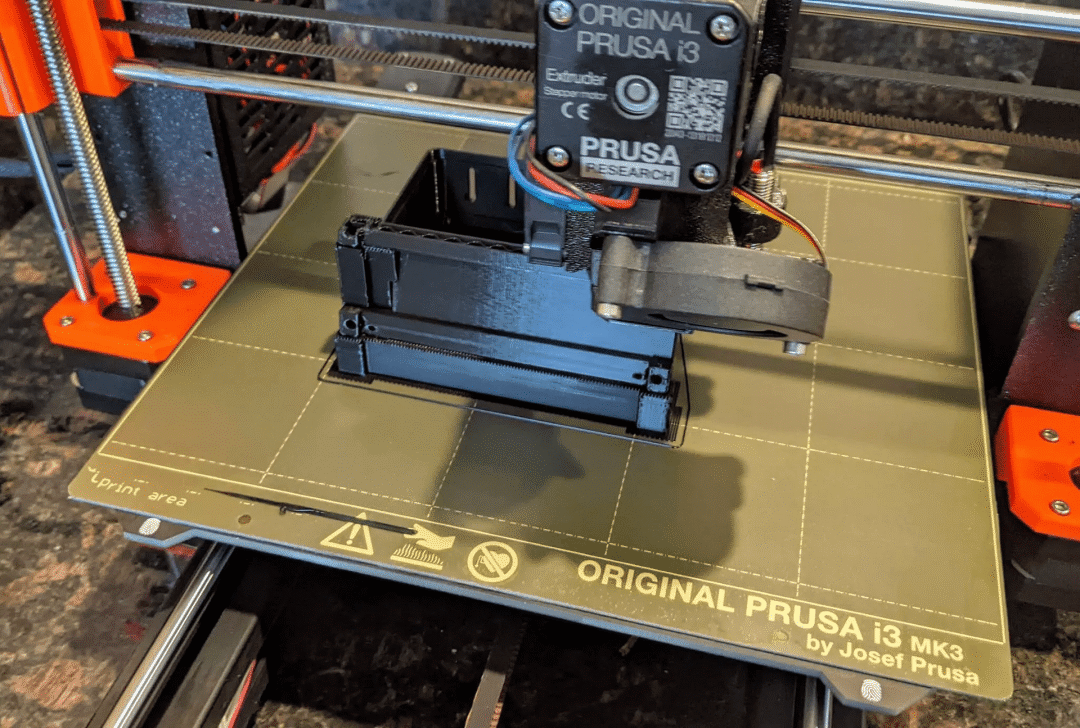
I use 0.2 The main structure is printed with a layer height of mm . In my 3D On the printer , Printing took 5 A little over an hour .
I use OpenSCAD Of "projection"[10] function , Created for the top cover and front panel 2D DXF file .
I usually use a name called "Carbide Create"[11] Free program for , Made for CNC machine tools G Code . But the panel has a 45 Degree chamfer , and Carbide Create Is a very basic program , Can't handle this problem well ( At least I Google the forums on their website , I came to this conclusion ). So I tried a different program , be called "CamBam"[12], It works very well .(CamBam It's not free , But it's free to use 40 Time )
The first 13 Step : appendix A: Clock drift correction ( Optional )
Yours 32k/CPU Crystals are not perfect . When GPS On , It will correct the drift . But if the drift is bad or your GPS The signal is not good , You can also apply a correction to the firmware . Currently this requires building code . stay main.c At the top of the , There are some definitions that have been commented out .
// Clock drift correction
// If your clock runs too fast or too slow, then you can enable these
//#define CORRECT_CLOCK_DRIFT
// number of seconds that a second should be added or removed
//#define CLOCK_DRIFT_SECONDS_PER_CORRECT 1800
// define this if the clock is too slow, otherwise leave it commented out
//#define CLOCK_DRIFT_TOO_SLOW
You can cancel the above two #define Remarks of statements , To enable calibration .
Just cancel the CLOCK_DRIFT_TOO_SLOW Notes ( If your clock is already slow ).
If your clock is too fast , Don't comment . The only thing to do is set up CLOCK_DRIFT_SECONDS_PER_CORRECT...
Mathematical methods
Waited about a day , Then see how much the clock has drifted . for example , You may have to wait 23 Hours . If you see the clock slow 10 second , Then your revision will be .
(3600 * 23) / 10 = 8280 second , Each correction .
#define CORRECT_CLOCK_DRIFT
#define CLOCK_DRIFT_SECONDS_PER_CORRECT 8280
#define CLOCK_DRIFT_TOO_SLOW
Non mathematical methods
Just try one like 5000 Numbers like this , And perfect the clock when you notice that it is still too fast or too slow . Or too slow ? try 2,500. It's too fast ? try 10,000. Keep records , And repeatedly improve to an acceptable value , Just like the number guessing game you may have played at some time .
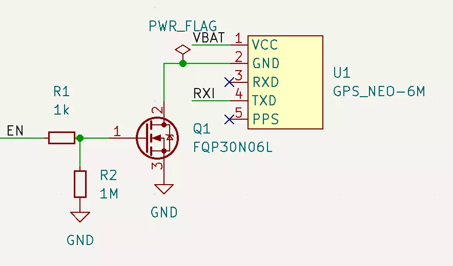
The first 14 Step : appendix B: cheap GPS Power control ( About BS170 N-MOSFET)
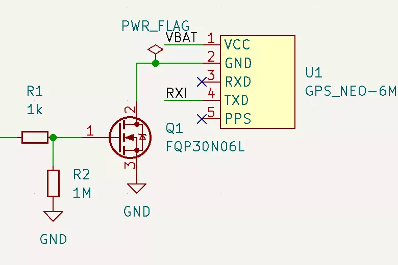

Go over Step four " cheap GPS " The power control circuit described in , The above power cut-off circuit is called "low side switch". Its advantage is that it is easier to understand , And the number of parts is small . For all that , There are still some design problems .
GPS The ground wire of is not connected to GND Connected to a , But with MOSFET Connected to a . This means from GPS To the microcontroller UART The signal will have MOSFET The pressure drop is added to it (Vds), Increased noise sensitivity , And may cause errors .
If your microcontroller input is specified as 3.3V The maximum of , You wouldn't want to use this design ( I choose the ATMega328P There is no such restriction ).
3.3V( above EN Pin ) For each MOSFET It's not a very strong starting voltage .
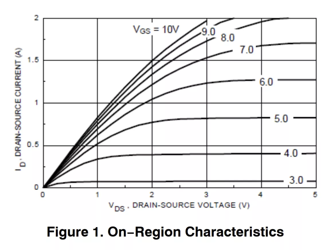
however ,UART It's a digital signal , The difference between the ground wires is not great , So maybe it will work anyway ? I tried , And it works very well ...... At first , But over time , I gradually found it unreliable . To understand why , Let's refer to my original choice BS170 As my N-MOSFET Characteristic curve of [13].
stay X The shaft 3.3V when , We will sit on the 3.0 and 4.0V Between lines . therefore , Maybe we'll get 100mA? Maybe enough ?
The multimeter tells me ,GPS Consume 40-60mA, But I think this is an average . according to GPS Trying to do something , It just needs more current than a transistor can allow , therefore GPS Land (MOSFET Drain electrode ) The voltage will rise . This has resulted in UART error , Lowers the GPS The overall voltage of the device , and GPS Sometimes the device still works , Sometimes it will enter the reset cycle .
One solution is to use a "high side" Power circuit , Add one to it P-MOSFET To achieve this goal . See the schematic diagram above . This eliminates the problem of separate grounding , And provide a complete 5V( The battery ) Grid voltage fluctuation , This will make it relevant P-MOSFET Fully open .
here [14] yes falstad A high side design example in .
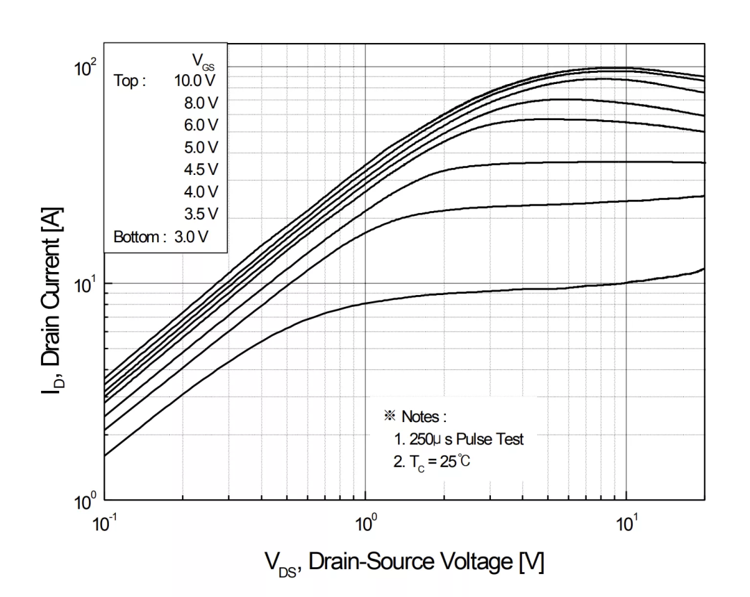
At present, I have ordered one with low-end cabling PCB, So my secondary solution is to give up BS170, While using FQP30N06L Instead of . This higher current MOSFET( Maximum 30A!) There seems to be a serious surplus , And it does , But the curve looks much better . stay 3.3V Under voltage , There are about 10A The current margin of , Than BS170 Improved 100 times , It should be enough now ; And there is no return to instability .
Reference material
[1]
falstad: http://www.falstad.com/circuit/circuitjs.html?ctz=CQAgjCAMB0l3BWcMBMcUHYMGZIA4UA2ATmIxAUgoqoQFMBaMMAKADMLiUQUAWKwvx5Ds3MNCQwELAEoUMhEIIphuyqlSGSoUCSwBOSoczVCUfHZRYAPJQnJpeIDJAeuQTiwHEACgGUWACMlfHAUPGcwRRQwJ0gWAHd5RWVBATjEo3Ss8FUoFgBzHJQEFJFIOPzDBC5hTWJooSoweFkPZT5NUTqdTSpsaGxe3WkAZ3bPIV4GnuaQNgBDABtRugMPGc6NxVENZHg4Qu2QXePsbEUNFiA
[2]Arduino: https://www.arduino.cc/
[3]avr-gcc Tools : https://www.pololu.com/docs/0J61/6.3
[4]epaper project : https://github.com/mattwach/epaper_clock
[5]firmware Catalog : https://github.com/mattwach/epaper_clock/tree/main/firmware
[6]Makefile: https://github.com/mattwach/epaper_clock/blob/main/src/Makefile
[7]src/gps.c: https://github.com/mattwach/epaper_clock/blob/main/src/gps.c
[8]https://www.nongnu.org/avrdude/: https://www.nongnu.org/avrdude/
[9]schematic/: https://github.com/mattwach/epaper_clock/tree/main/schematic
[10]projection function : https://en.wikibooks.org/wiki/OpenSCAD_User_Manual/Using_the_2D_Subsystem#3D_to_2D_Projection
[11]Carbide Create: https://carbide3d.com/carbidecreate/
[12]CamBam: http://www.cambam.info/
[13]N-MOSFET Characteristic curve of : https://www.onsemi.com/pdf/datasheet/mmbf170-d.pdf
[14]falstad A high side design example in : http://www.falstad.com/circuit/circuitjs.html?ctz=CQAgjCAMB0l3BWcMBMcUHYMGZIA4UA2ATmIxAUgoqoQFMBaMMAKADMLiUQUAWKwvx5Ds3MNCQxIKdiEFUwGQnKFgUeELwjjJsGQCcVCpRULHlC+JBYB3OX3DrTCp9bsIzjjR-NQWAJWcvTWJlNQ0qKiFJKCgJFkMMNHATJKp1CJoWAA8QHHIiDQw8AowIXmEQAHEABQBlFgAjOTwNMC480J5ivwBzPOSMgapRSL87Qg9gtOC3YenkxQtbIxTleR4Ha36NlCmN3ArIhM5uPiiu89iweADNQWEo0UfYqJHobFe4hBYAZ3uKldeJchAoQGwAIYAG1+dBYQA
First translation :DF Maker community
For reprint, please indicate the original author and source

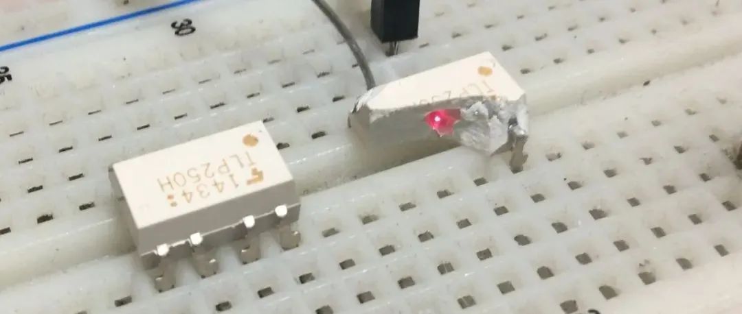
Seemingly simple optocoupler circuit , What should we pay attention to in actual use ?
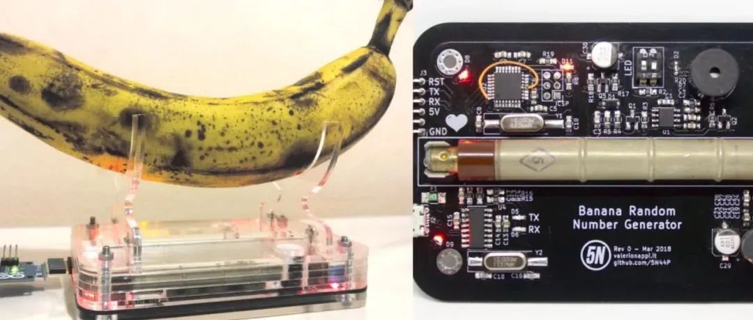
what ? Banana can make a true random number generator ? The project is open source
I'm brother Lao Yu , An electronic engineer who loves learning
Pay attention to me , Become better together !
Welcome to share 、 Collection 、 give the thumbs-up 、 Looking at .
边栏推荐
- Learn tla+ (XII) -- functions through examples
- pytorch fine-tuning (funtune) : 镂空设计or 偷梁换柱
- Process scheduling and termination
- What sparks can applet container technology collide with IOT
- [Chongqing Guangdong education] National Open University spring 2019 1042 international economic law reference questions
- Restful fast request 2022.2.1 release, support curl import
- One click generation and conversion of markdown directory to word format
- Database postragesq PAM authentication
- 172. Zero after factorial
- 流批一体在京东的探索与实践
猜你喜欢
Hedhat firewall

Comment mettre en place une équipe technique pour détruire l'entreprise?
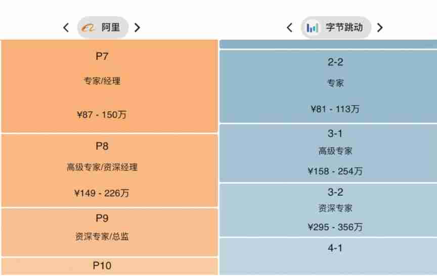
He was laid off.. 39 year old Ali P9, saved 150million

MATLB|多微电网及分布式能源交易

微信小程序:独立后台带分销功能月老办事处交友盲盒
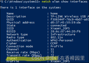
Win:使用 PowerShell 检查无线信号的强弱
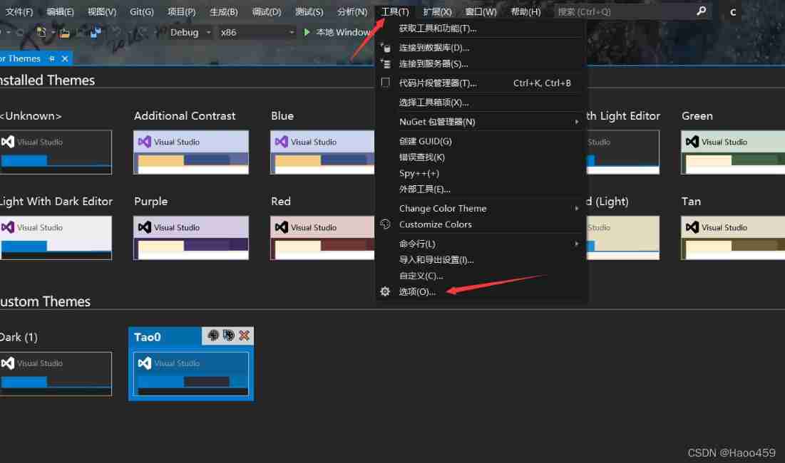
Visual studio 2019 set transparent background (fool teaching)

. Net starts again happy 20th birthday
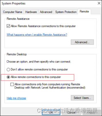
Win:使用 Shadow Mode 查看远程用户的桌面会话
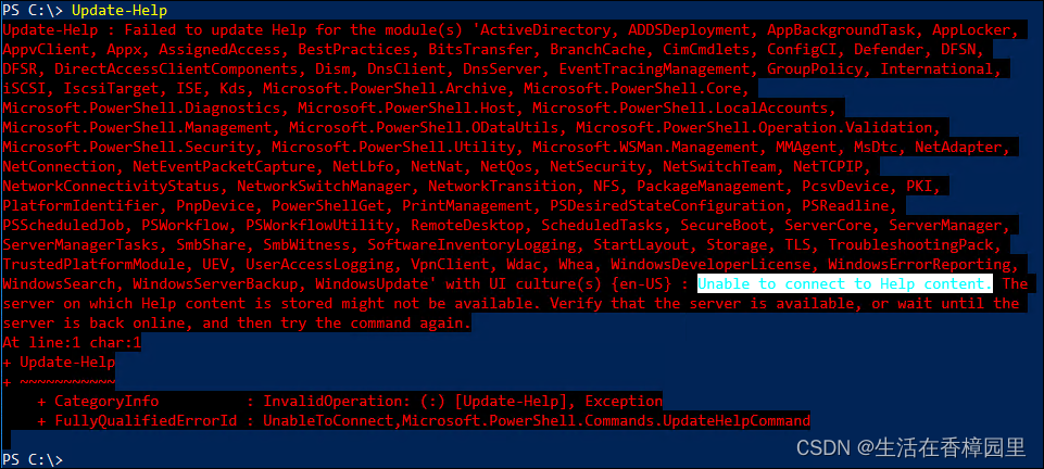
PowerShell:在代理服务器后面使用 PowerShell
随机推荐
Package What is the function of JSON file? What do the inside ^ angle brackets and ~ tilde mean?
Classification of performance tests (learning summary)
Express routing, express middleware, using express write interface
Nebula Importer 数据导入实践
"2022" is a must know web security interview question for job hopping
Tla+ through examples (XI) -- propositional logic and examples
Valentine's Day flirting with girls to force a small way, one can learn
Grpc message sending of vertx
微信小程序:微群人脉微信小程序源码下载全新社群系统优化版支持代理会员系统功能超高收益
phpstrom设置函数注释说明
RichView TRVStyle MainRVStyle
MySQL regexp: Regular Expression Query
JVM's responsibility - load and run bytecode
220213c language learning diary
Numpy library introductory tutorial: basic knowledge summary
MATLB|多微电网及分布式能源交易
Four pits in reentrantlock!
Vulnstack3
Database postragesq PAM authentication
Redis' hyperloglog as a powerful tool for active user statistics