当前位置:网站首页>Assembly and interface technology experiment 5-8259 interrupt experiment
Assembly and interface technology experiment 5-8259 interrupt experiment
2022-07-06 22:11:00 【dor. yang】
One 、 The experiment purpose
The experiment enables students to master 8259 The hardware connection of vector interrupt mode and the method of software programming , At the same time, make students master the method of interrupt and other interface chips to complete a specific task .
Two 、 Experimental content
1、 Manually generate a single pulse as an interrupt request signal connected to MIRQ3( Corresponding interrupt number 0BH) Shanghe SIRQ10( Corresponding interrupt number 72H) On . Each time the switch is pressed, an interrupt is generated , some LED The light goes on or off once ( Last time it was on , Now it's gone ; Last time out , Now it's on ), interrupt 10 After times, the program exits . among , Lord 8259 The port address of is 20H, Slave piece 8259 The port address of is 0A0H.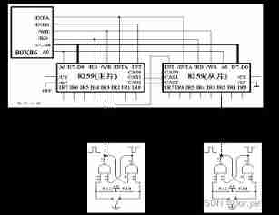
attachment :
Bus /MIRQx Pick up Single pulse 1/ Positive pulse
Bus /SIRQx Pick up Single pulse 2/ Positive pulse
Programming tips
(1) MIRQ3 and SIRQ10 It's to receive PC Standard interrupt 8259, Its initialization has been carried out by BIOS complete , Therefore, there is no need to deal with master and slave 8259A initialization (ICW1-ICW4), But it is necessary to set the interrupt vector and open the interrupt ( Include CPU Break and 8259A interrupt ) Wait for the operation ; Be careful : Non automatic termination is adopted in microcomputer , Before the interruption ends ( The last of the interrupt service program ) Send the interrupt end command . in addition 、 Write interrupt mask words in “ read — modify — Write ” The process , As follows :
IN	AL,21H
AND	AL,0DFH
OUT	21H,AL
(2) System interrupt main interrupt MIRQ3
(3) System interrupt from interrupt SIRQ10.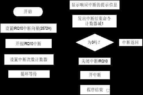
2、8255 Of PC6 Connect to as an interrupt source MIRQ3 On , Every direction 8259A Make an interrupt request , send LED The indication is alternately on and off . interrupt 5 After times, the program exits .
Programming tips
(1) The main function of the interrupt service program is to turn on and off alternately LED Indicator light ( That is to say 1 The second advance interrupt is on LED,
The first 2 The second advance interrupt goes out LED).8255 You need to initialize in the main program before using .
(2) 8255 Of PC6 As interrupt source , It should be triggered by rising edge ( From low to high ), In order to be able to make the next interruption ,PC6 It must become low and flat .
(3) In order to make LED The flicker of is visible , Add a delay procedure between interrupting applications .
experiment 1 The flow chart of the procedure is as follows :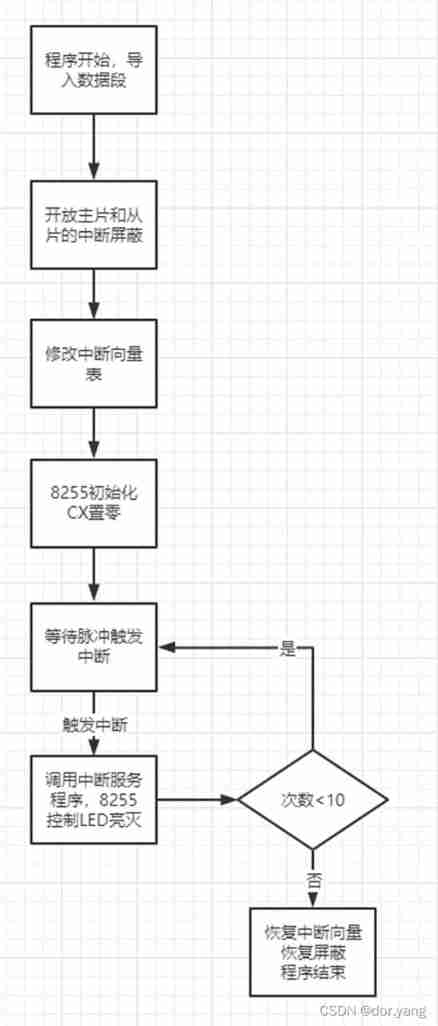
experiment 2 The flowchart is as follows :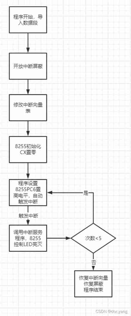
3、 ... and 、 The experimental steps
1、 Connect the experimental circuit according to the schematic diagram ( Need to connect the red line ).
experiment 1 The wiring diagram is as follows :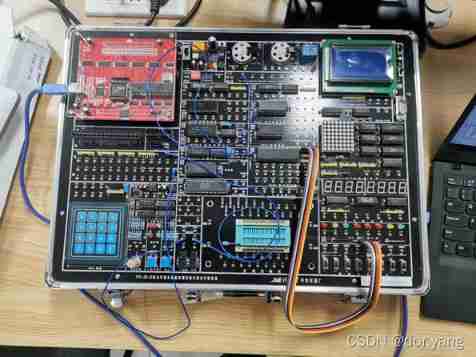
experiment 2 The wiring diagram is as follows :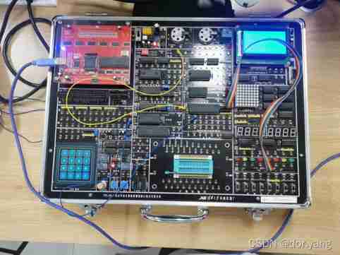
2、 Correctly understand the experimental principle .
3、 Write the experimental program , And debugging on the computer , Observe the results of the experiment .
answer : experiment 1: The master slice and the slave slice correspond to one LED The lamp , Interrupt is triggered by pulse , Every time you trigger , Corresponding LED The lights are alternately on or off , stay 10 After times, the program exits .
experiment 1 The code for is as follows :
SSEG SEGMENT
    DW 100 DUP(?)
SSEG ENDS

; Set the variable to save the interrupt vector address
DSEG SEGMENT
    OLD1_OFF DW ?
    OLD1_SEG DW ?
    OLD2_OFF DW ?
    OLD2_SEG DW ?
; The topic requires interruption 10 Time , Set variables for comparison
    N DW 10
; adopt 8255 Set up LED Light on position
    LED1 DW 00000100B
    LED2 DW 00100000B
DSEG ENDS

CSEG SEGMENT
    ASSUME CS:CSEG,DS:DSEG,SS:SSEG
START:
    MOV AX,DSEG
    MOV DS,AX

; Open the interrupt shielding of the main chip
    CLI
    IN AL,21H
    AND AL,0F3H	;11110011
    OUT 21H,AL

; Open interrupt shielding of slave
    IN AL,0A1H
    AND AL,0FBH	;11111011
    OUT 0A1H,AL

; Interrupt the main program
    CALL SET_TABLE
; To be used 8255 To initialize
    MOV DX,283H		;8255 Command port address of
    MOV AL,90H		; Use 0 The way
    OUT DX,AL		; Send it to the command port
; Interrupt the program
    XOR CX,CX
; Count the number of interrupts , exceed 10 Once, exit
S1:
    STI
    HLT
    CMP CX,N
    JNZ S1
; End of interruption , Resume interrupt vector
    CLI
    CALL RECOVER_TABLE
; Interrupt end Recovery Mask
    IN AL,21H
    OR AL,0CH		;00001100
    OUT 21H,AL
    IN AL,0A1H
    OR AL,04H		;00000100
    OUT 0A1H,AL
    STI
    MOV AH,4CH		; Program end
    INT 21H

; Modify interrupt vector
SET_TABLE PROC
    PUSH DS
    PUSH DI
    PUSH BX

    MOV AX,0;
    MOV DS,AX
    MOV DI,4*0BH
    ; Get the original interrupt vector
    MOV BX,[DI]
    MOV OLD1_OFF,BX
    MOV BX,[DI+2]
    MOV OLD1_SEG,BX
    ; Set a new interrupt vector
    MOV BX,OFFSET SW1_INT
    MOV [DI],BX
    MOV BX,SEG SW1_INT
    MOV [DI+2],BX

    MOV DI,4*72H
    ; Get the original interrupt vector
    MOV BX,[DI]
    MOV OLD2_OFF,BX
    MOV BX,[DI+2]
    MOV OLD2_SEG,BX
    ; Set a new interrupt vector
    MOV BX,OFFSET SW2_INT
    MOV [DI],BX
    MOV BX,SEG SW2_INT
    MOV [DI+2],BX

    POP BX
    POP DI
    POP DS
    RET
SET_TABLE ENDP

; Interrupt vector recovery
RECOVER_TABLE PROC
    PUSH DS
    PUSH DI
    PUSH BX

    MOV AX,0;
    MOV DS,AX
    MOV DI,4*0BH
    ; Implement interrupt vector recovery statement
    MOV BX,OLD1_OFF
    MOV [DI],BX
    MOV BX,OLD1_SEG
    MOV [DI+2],BX

    MOV DI,4*72H
    ; Implement interrupt vector recovery statement
    MOV BX,OLD2_OFF
    MOV [DI],BX
    MOV BX,OLD2_SEG
    MOV [DI+2],BX

    POP BX
    POP DI
    POP DS
    RET
RECOVER_TABLE ENDP

; Interrupt service routine
SW1_INT PROC
    PUSH AX
    PUSH DX
    CLI
    INC CX			; Count the number of interrupts , If exceeded 10 Next time, the program exits
    MOV AX,LED1
    MOV DX,281H		;8255 Of B Address
    OUT DX,AX		; Send it to the command port
    XOR AX,00000100B	; XOR statements specify LED Corresponding output level conversion
    MOV LED1,AX
    MOV AL,20H
    OUT 20H,AL
    POP DX
    POP AX
    STI
    IRET
SW1_INT ENDP

; Another interrupt service program
SW2_INT PROC
    PUSH AX
    PUSH DX
    CLI
    INC CX			; Count the number of interrupts
    MOV AX,LED2
    MOV DX,281H		;8255 Of B Address
    OUT DX,AX		; Send it to the command port
    XOR AX,00100000B	; XOR statements specify LED Corresponding output level conversion
    MOV LED2,AX
    MOV AL,20H
    OUT 20H,AL
    MOV AL,20H;?
    OUT 0A0H,AL;?
    POP DX
    POP AX
    STI
    IRET
SW2_INT ENDP
CSEG ENDS
END START
experiment 2: In the process 8255 Of PC6 Control , The program automatically triggers an interrupt . The visible result is 8 individual LED The lights go on and off five times .
experiment 2 The code for is as follows :
SSEG SEGMENT
    DW 100 DUP(?)
SSEG ENDS

; Data segment , Storage LED operation , Interrupt vector and interrupt number standard
DSEG SEGMENT
    OLD_OFF DW ?
    OLD_SEG DW ?
    N DW 5
    LED DB 0FFH
DSEG ENDS

CSEG SEGMENT
    ASSUME CS:CSEG,DS:DSEG,SS:SSEG
START:
    MOV AX,DSEG
    MOV DS,AX

; Open interrupt mask
    CLI
    IN AL,21H
    AND AL,0F3H	;11110011
    OUT 21H,AL

; Interrupt the main program
    CALL SET_TABLE
; Yes 8255 To initialize
    MOV DX,283H
    MOV AL,90H
    OUT DX,AL
; Interrupt the program
    XOR CX,CX	;CX Zero clearing
S1:
    STI
    ; Set up 8255 Of PC6 Output high level , Trigger interrupt
    MOV DX,282H
    MOV AL,40H	;01000000
    OUT DX,AL
;LED
    MOV DX,281H
    MOV AL,0FFH
    OUT DX,AL
    CALL DELAY
    MOV AL,00H
    OUT DX,AL
    CALL DELAY
    MOV DX,282H
    MOV AL,00H
    OUT DX,AL
    ; Count the number of interrupts
    CMP CX,N
    JNZ S1
; End of interruption , Resume interrupt vector
    CLI
    CALL RECOVER_TABLE
; Interrupt end resume interrupt mask
    IN AL,21H
    OR AL,0CH
    OUT 21H,AL
    STI
    MOV AH,4CH
    INT 21H

; Modify interrupt vector
SET_TABLE PROC
    ; Register stack protection
    PUSH DS
    PUSH DI
    PUSH BX

    MOV AX,0;
    MOV DS,AX
    MOV DI,4*0BH
    ; Get the original interrupt vector
    MOV BX,[DI]
    MOV OLD_OFF,BX
    MOV BX,[DI+2]
    MOV OLD_SEG,BX
    ; Set a new interrupt vector
    MOV BX,OFFSET SW_INT
    MOV [DI],BX
    MOV BX,SEG SW_INT
    MOV [DI+2],BX

    POP BX
    POP DI
    POP DS
    RET
SET_TABLE ENDP

; Interrupt vector recovery
RECOVER_TABLE PROC
    PUSH DS
    PUSH DI
    PUSH BX

    MOV AX,0;
    MOV DS,AX
    MOV DI,4*0BH
    ; Realize interrupt vector recovery sentence
    MOV BX,OLD_OFF
    MOV [DI],BX
    MOV BX,OLD_SEG
    MOV [DI+2],BX

    POP BX
    POP DI
    POP DS
    RET
RECOVER_TABLE ENDP

; Interrupt service routine
SW_INT PROC
    PUSH AX
    PUSH DX
    CLI
    INC CX		; Count the number of interrupts

    MOV AL,20H
    OUT 20H,AL
    POP DX
    POP AX
    STI
    IRET
SW_INT ENDP

; Because the purpose of the program is LED Spontaneous flicker , Set the time delay to ensure the observation effect
DELAY PROC
    PUSH BX
    PUSH CX
    MOV CX,0FFFH
DL1:
    MOV BX,0FFFH
DL2:
    DEC BX
    JNZ DL2
    DEC CX
    JNZ DL1
    POP CX
    POP BX
    RET
DELAY ENDP

CSEG ENDS
END START
Four 、 Thinking questions
How to understand real-time control by interruption , Please give some possible application examples .
answer : Interrupt is a kind of CPU Technology of communicating with hardware devices . for example , When we are tapping the keyboard , Keyboard controller ( The hardware device that controls the keyboard ) Will send an interrupt , Notify the operating system that a key has been pressed . essentially , An interrupt is a special signal , From the hardware device to CPU send out . When CPU After receiving the interrupt signal , Will immediately notify the operating system of the arrival of this signal , Then the operating system is responsible for processing these new data .
边栏推荐
- 十二、启动流程
- zabbix 代理服务器 与 zabbix-snmp 监控
- Common sense: what is "preservation" in insurance?
- 美国科技行业结束黄金时代,芯片求售、裁员3万等哀声不断
- AI enterprise multi cloud storage architecture practice | Shenzhen potential technology sharing
- Record the process of cleaning up mining viruses
- GPS从入门到放弃(十四)、电离层延时
- GPS从入门到放弃(二十)、天线偏移
- Unity3d Learning Notes 6 - GPU instantiation (1)
- Leetcode learning records (starting from the novice village, you can't kill out of the novice Village) ---1
猜你喜欢

Xiaoman network model & http1-http2 & browser cache

Common sense: what is "preservation" in insurance?
GPS從入門到放弃(十三)、接收機自主完好性監測(RAIM)
GPS from entry to abandonment (XIV), ionospheric delay
2021 geometry deep learning master Michael Bronstein long article analysis
Management background --4, delete classification

AI 企业多云存储架构实践 | 深势科技分享
二叉(搜索)树的最近公共祖先 ●●
![[asp.net core] set the format of Web API response data -- formatfilter feature](/img/95/b7e7b5e9e9ac1d9295c17640beccb3.jpg)
[asp.net core] set the format of Web API response data -- formatfilter feature

LeetCode:1189. The maximum number of "balloons" -- simple
随机推荐
Maximum product of three numbers in question 628 of Li Kou
How does the uni admin basic framework close the creation of super administrator entries?
GPS从入门到放弃(十三)、接收机自主完好性监测(RAIM)
GPS from getting started to giving up (XI), differential GPS
MPLS experiment
【sdx62】WCN685X将bdwlan.bin和bdwlan.txt相互转化操作方法
插入排序与希尔排序
Write a rotation verification code annotation gadget with aardio
Powerful domestic API management tool
二叉(搜索)树的最近公共祖先 ●●
Persistence / caching of RDD in spark
Unity3d Learning Notes 6 - GPU instantiation (1)
Method return value considerations
小满网络模型&http1-http2 &浏览器缓存
Adjustable DC power supply based on LM317
Shell product written examination related
The underlying implementation of string
Unity3D学习笔记6——GPU实例化(1)
C # réalise la liaison des données du rapport Crystal et l'impression du Code à barres 4
CCNA-思科网络 EIGRP协议