当前位置:网站首页>GPS from getting started to giving up (XX), antenna offset
GPS from getting started to giving up (XX), antenna offset
2022-07-06 21:56:00 【Chasing wind】
Antenna offset (Antenna Offsets) It refers to the offset between the phase center of the antenna and the centroid of the object , This offset will bring centimeter error to satellite positioning . In general positioning , This error can be ignored , But in precision positioning , The effect of this error needs to be eliminated . The concept of center of mass has been learned in physics in Middle School , Not much to say . Here explain the antenna phase center . The electromagnetic wave radiated by the antenna leaves the antenna at a certain distance , Its isophase plane will be approximately a sphere , The spherical center of the sphere is the equivalent phase center of the antenna , That is, the antenna phase center (Antenna Phase Center ). The phase center of the antenna is a theoretical point , in other words , Theoretically, the signal radiated by the antenna is radiated outward with this point as the center .
Antenna offset includes satellite antenna offset and receiver antenna offset .
One 、 Satellite antenna offset
Satellite antenna offset (Satellite Antenna Offsets) It refers to the offset between the antenna phase center of the satellite and the satellite centroid . In precise positioning , We need a precise ephemeris .IGS The precise ephemeris provided is relative to the centroid of the satellite , and GPS The navigation message of is relative to the phase center of the antenna , We must consider the difference between the two in our calculation . The measured value is obtained from the received signal , So its value is relative to the phase center of the antenna . After knowing the satellite antenna offset , We can convert all values into the relative phase center of the antenna , This is convenient for the later positioning solution .
Then we don't make satellites , How to know the antenna offset of the satellite ? In theory , Only those who make satellites know the satellite antenna offset , And each satellite may be different . Fortunately, we have IGS. Satellite antenna offset data will be reported to IGS, and IGS Uniformly arrange and release all satellite antenna offset data . Data can be obtained from IGS Of ftp Server download , The address is ftp://ftp.igs.org/pub/station/general/.
IGS There are mainly two documents related to satellite antenna offset provided :rcvr_ant.tab and igs14.atx
rcvr_ant.tab
The content of this document is IGS Naming rules for each device , Such as receiver 、 The antenna 、 Radome 、 Satellite antenna, etc . Only qualified names can be used in IGS Among the various documents provided by the station . let me put it another way , If in IGS I saw some confused names in some documents of , You can also find the corresponding meaning in this file .
igs14.atx
This is a symbolic link file , Link to the latest modified igs14_wwww.atx file , there wwww Express GPS Weeks . This file contains satellite and receiver antenna phase correction values , be based on IGS14 Earth reference frame .
atx The format of the document is Antenna Exchange Format (ANTEX), stay antex14.txt There is a detailed description of this format in the document (antex14.txt Documents can also be found in IGS Of ftp Server download ), Here is a brief introduction .
The following content is intercepted igs14.atx Part of :
                                                            START OF ANTENNA
BLOCK IIF           G01                 G063      2011-036A TYPE / SERIAL NO
                                             0    29-JAN-17 METH / BY / # / DATE
     0.0                                                    DAZI
     0.0  17.0   1.0                                        ZEN1 / ZEN2 / DZEN
     2                                                      # OF FREQUENCIES
  2011     7    16     0     0    0.0000000                 VALID FROM
IGS14_2082                                                  SINEX CODE
   G01                                                      START OF FREQUENCY
    394.00      0.00   1501.80                              NORTH / EAST / UP
   NOAZI    6.10    4.40    2.80    1.30   -0.20   -1.40   -2.80   -3.90   -4.40   -4.40   -3.70   -2.30   -0.20    3.00    5.70   12.40   18.20   23.50
   G01                                                      END OF FREQUENCY
   G02                                                      START OF FREQUENCY
    394.00      0.00   1501.80                              NORTH / EAST / UP
   NOAZI    6.10    4.40    2.80    1.30   -0.20   -1.40   -2.80   -3.90   -4.40   -4.40   -3.70   -2.30   -0.20    3.00    5.70   12.40   18.20   23.50
   G02                                                      END OF FREQUENCY
                                                            END OF ANTENNA
This is a GPS In the system PRN by 01 Satellite antenna offset data . from “# OF FREQUENCIES” In this line, we know that it has 2 Frequency . For the first frequency ,“NORTH / EAST / UP” The three numbers in this line are the offset values in three directions , In millimetres .“ZEN1 / ZEN2 / DZEN” This line shows the range of the bottom of the sky from ZEN1 To ZEN2,DZEN Step length ,“NOAZI” In this line, the corresponding phase center change value is given according to the range and step size of the sky bottom angle (pcv: phase center variations). Take the first frequency as an example ,“NOAZI” Yes 18 It's worth , Corresponding “ZEN1 / ZEN2 / DZEN” The bottom of the sky 0.0 C to 17.0 degree , step 1.0 degree , Is just ( Z E N 2 − Z E N 1 ) / D Z E N = 18 (ZEN2-ZEN1)/DZEN=18(ZEN2−ZEN1)/DZEN=18 It's worth .“DAZI” The value of this line is 0.0 It indicates that the antenna offset data of this satellite is independent of azimuth (non-azimuth-dependent).“NOAZI” It also represents the value independent of azimuth . If it depends on azimuth , be “DAZI” Step length ,“NOAZI” There will be 360 / D A Z I 360/DAZI360/DAZI That's ok , Every line also has ( Z E N 2 − Z E N 1 ) / D Z E N (ZEN2-ZEN1)/DZEN(ZEN2−ZEN1)/DZEN It's worth , The change value of phase center corresponding to a azimuth at different nadir angles . Because the step resolution is limited , So in practical application , If the angle is between two values , Then it can be calculated by interpolation .
stay RTKLIB in , By calling readantex Function to parse atx Of documents , Here's the code , The process is straightforward , There's not much to explain .
static int readantex(const char *file, pcvs_t *pcvs)
{
    FILE *fp;
    static const pcv_t pcv0={0};
    pcv_t pcv;
    double neu[3];
    int i,f,freq=0,state=0,freqs[]={1,2,5,6,7,8,0};
    char buff[256];

    trace(3,"readantex: file=%s\n",file);

    if (!(fp=fopen(file,"r"))) {
        trace(2,"antex pcv file open error: %s\n",file);
        return 0;
    }
    while (fgets(buff,sizeof(buff),fp)) {

        if (strlen(buff)<60||strstr(buff+60,"COMMENT")) continue;

        if (strstr(buff+60,"START OF ANTENNA")) {
            pcv=pcv0;
            state=1;
        }
        if (strstr(buff+60,"END OF ANTENNA")) {
            addpcv(&pcv,pcvs);
            state=0;
        }
        if (!state) continue;

        if (strstr(buff+60,"TYPE / SERIAL NO")) {
            strncpy(pcv.type,buff   ,20); pcv.type[20]='\0';
            strncpy(pcv.code,buff+20,20); pcv.code[20]='\0';
            if (!strncmp(pcv.code+3,"        ",8)) {
                pcv.sat=satid2no(pcv.code);
            }
        }
        else if (strstr(buff+60,"VALID FROM")) {
            if (!str2time(buff,0,43,&pcv.ts)) continue;
        }
        else if (strstr(buff+60,"VALID UNTIL")) {
            if (!str2time(buff,0,43,&pcv.te)) continue;
        }
        else if (strstr(buff+60,"START OF FREQUENCY")) {
            if (sscanf(buff+4,"%d",&f)<1) continue;
            for (i=0;i<NFREQ;i++) if (freqs[i]==f) break;
            if (i<NFREQ) freq=i+1;
        }
        else if (strstr(buff+60,"END OF FREQUENCY")) {
            freq=0;
        }
        else if (strstr(buff+60,"NORTH / EAST / UP")) {
            if (freq<1||NFREQ<freq) continue;
            if (decodef(buff,3,neu)<3) continue;
            pcv.off[freq-1][0]=neu[pcv.sat?0:1]; /* x or e */
            pcv.off[freq-1][1]=neu[pcv.sat?1:0]; /* y or n */
            pcv.off[freq-1][2]=neu[2];           /* z or u */
        }
        else if (strstr(buff,"NOAZI")) {
            if (freq<1||NFREQ<freq) continue;
            if ((i=decodef(buff+8,19,pcv.var[freq-1]))<=0) continue;
            for (;i<19;i++) pcv.var[freq-1][i]=pcv.var[freq-1][i-1];
        }
    }
    fclose(fp);

    return 1;
}
For the calculation of satellite antenna offset correction value ,RTKLIB Is called satantpcv Function . Personally, I think there is something wrong with this function , Only phase center variations, Without considering phase center offset.
Two 、 Receiver antenna offset
There are many similarities between receiver antenna offset and satellite antenna offset , Also use IGS The two documents provided :rcvr_ant.tab and igs14.atx.rcvr_ant.tab There is the name of the receiver ,igs14.atx There is receiver antenna offset data in .
The difference is , The receiver has another file antenna.gra, It provides the antenna reference point of the receiver (ARP: antenna reference point) And North reference point (NRP: north reference point) The definition of , And the physical size of the antenna . This is a plain text file , However, there are schematic diagrams of various antennas , I have to show my admiration to the cartographer , Interested students can go to see it by themselves .
In the algorithm, , When calculating the antenna offset of the receiver, we should not only consider the satellite antenna offset phase center offset and phase center variations, Also consider the position of the antenna reference point of the receiver . If in RTKLIB in , It's through antmodel Function to calculate the antenna offset correction value of the receiver , The code is as follows . among del Is the offset value relative to the antenna reference point ,azel Is azimuth and pitch angle ,pcv->off by phase center offset,pcv->var by phase center variations.
void antmodel(const pcv_t *pcv, const double *del, const double *azel,
                     int opt, double *dant)
{
    double e[3],off[3],cosel=cos(azel[1]);
    int i,j;

    trace(4,"antmodel: azel=%6.1f %4.1f opt=%d\n",azel[0]*R2D,azel[1]*R2D,opt);

    e[0]=sin(azel[0])*cosel;
    e[1]=cos(azel[0])*cosel;
    e[2]=sin(azel[1]);

    for (i=0;i<NFREQ;i++) {
        for (j=0;j<3;j++) off[j]=pcv->off[i][j]+del[j];

        dant[i]=-dot(off,e,3)+(opt?interpvar(90.0-azel[1]*R2D,pcv->var[i]):0.0);
    }
    trace(5,"antmodel: dant=%6.3f %6.3f\n",dant[0],dant[1]);
}边栏推荐
- From campus to Tencent work for a year of those stumbles!
- Yyds dry goods inventory C language recursive implementation of Hanoi Tower
- Leetcode topic [array] -118 Yang Hui triangle
- uni-app App端半屏连续扫码
- 11、 Service introduction and port
- Web开发小妙招:巧用ThreadLocal规避层层传值
- GPS从入门到放弃(十四)、电离层延时
- Guava: use of multiset
- 爬虫实战(五):爬豆瓣top250
- Method return value considerations
猜你喜欢
guava:Collections.unmodifiableXXX创建的collection并不immutable
红杉中国,刚刚募资90亿美元

麦趣尔砸了小众奶招牌
Efficiency tool +wps check box shows the solution to the sun problem
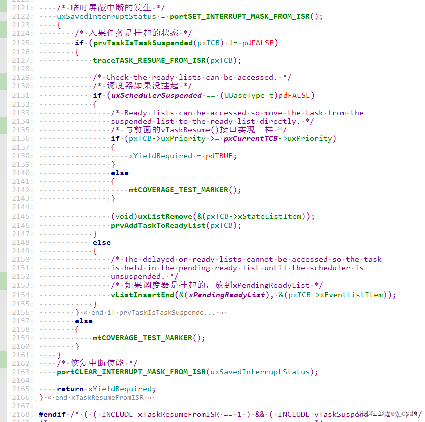
1292_ Implementation analysis of vtask resume() and xtask resume fromisr() in freeros
![Happy sound 2[sing.2]](/img/ca/1581e561c427cb5b9bd5ae2604b993.jpg)
Happy sound 2[sing.2]

Yuan Xiaolin: safety is not only a standard, but also Volvo's unchanging belief and pursuit
C# 如何在dataGridView里设置两个列comboboxcolumn绑定级联事件的一个二级联动效果
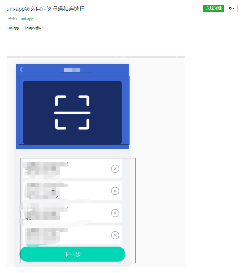
Uni app app half screen continuous code scanning
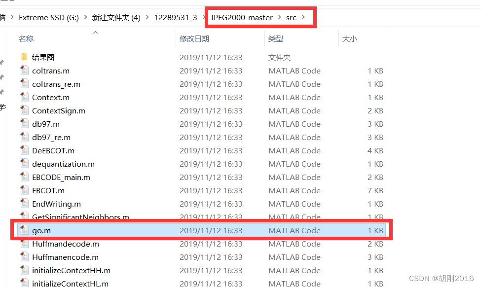
JPEG2000 matlab source code implementation
随机推荐
用aardio写一个旋转验证码标注小工具
JS method to stop foreach
Sparkshuffle process and Mr shuffle process
MySQL - 事务(Transaction)详解
Sdl2 source analysis 7: performance (sdl_renderpresent())
Numpy download and installation
强化学习-学习笔记5 | AlphaGo
Michael smashed the minority milk sign
基于LM317的可调直流电源
Efficiency tool +wps check box shows the solution to the sun problem
OpenCV300 CMake生成project在项目过程中的问题
[Li Kou brush questions] 32 Longest valid bracket
Checkpoint of RDD in spark
[Digital IC manual tearing code] Verilog automatic beverage machine | topic | principle | design | simulation
guava:Collections. The collection created by unmodifiablexxx is not immutable
Aggregate function with key in spark
The underlying implementation of string
guava:创建immutableXxx对象的3种方式
Comparison between multithreaded CAS and synchronized
LeetCode学习记录(从新手村出发之杀不出新手村)----1