当前位置:网站首页>PHY drive commissioning - phy controller drive (II)
PHY drive commissioning - phy controller drive (II)
2022-07-05 06:53:00 【Enlaihe】
1. Preface
Kernel version :linux 4.9.225, With freescale For example .
2. summary
PHY The chip is OSI The bottom of the - The physical layer (Physical Layer), adopt MII/GMII/RMII/SGMII/XGMII And other media independent interfaces ( Media independent interface ) Interface with data link layer MAC The chips are connected , And pass MDIO Interface implementation pair PHY Status monitoring 、 Configure and manage .
PHY And MAC General connection of the whole frame as follows ( This is from the Internet ):
PHY The composition of the whole hardware system is relatively complex ,PHY And MAC Connected to a ( It can also be connected through an intermediate device ),MAC And CPU Connected to a ( There are integrated in-house , There are also external ways ),PHY And MAC adopt MII and MDIO/MDC Connected to a ,MII Is to take the network data ,MDIO/MDC It's used to communicate with PHY Register communication , Yes PHY To configure .
PHY Driving and I2C/SPI The drive is the same , It is divided into Controller drive and Device driver . This section starts with controller drive .
3. PHY Overview of controller drive
PHY The controller drives and SPI/I2C Very similar , The core function of the controller is Realize specific reading and writing functions . The difference lies in PHY The implementation of the read-write function of the controller can be roughly divided into two ways ():
- Call directly CPU Of MDIO controller ( Call directly cpu The corresponding register ) The way
- adopt GPIO/ peripheral soc simulation MDIO The way of timing .
PHY The controller of is generally described as mdio_bus Platform equipment ( Be careful : This is a device , Equate to SPI/I2C Medium master equipment ; And the bus 、 drive 、 In the equipment bus It's not a concept ).
Since it is a platform device , Then there must be nodes in the device tree that can be resolved to platform devices , There should also be corresponding platform device drivers . And SPI Drive similar ,PHY The device model is also driven by the controller probe Function .
This article will cover both , Mainly the latter .
4. adopt GPIO/ peripheral soc simulation MDIO The way of timing
4.1 The general description of the controller platform device in the device tree ( Not exactly , It mainly describes the matching rules )
# linux-4.9.225\Documentation\devicetree\bindings\soc\fsl\cpm_qe\network.txt
* MDIO
Currently defined compatibles: fsl,pq1-fec-mdio (reg is same as first resource of FEC device) fsl,cpm2-mdio-bitbang (reg is port C registers)
Properties for fsl,cpm2-mdio-bitbang:
fsl,mdio-pin : pin of port C controlling mdio data
fsl,mdc-pin : pin of port C controlling mdio clock
Example: [email protected] {
	compatible = "fsl,mpc8272ads-mdio-bitbang",
				 "fsl,mpc8272-mdio-bitbang",
			     "fsl,cpm2-mdio-bitbang";
		reg = <10d40 14>;
		#address-cells = <1>;
		#size-cells = <0>;
		fsl,mdio-pin = <12>;
		fsl,mdc-pin = <13>;

	# linux-4.9.225\Documentation\devicetree\bindings\phy
	xxx_phy: [email protected] {                       // Describe the controller below PHY Node of the device
		reg = <0x0>;                             //PHY The address of
	};
};
4.2 Controller platform driver code walk
4.2.1 Registration of controller platform driver
static const struct of_device_id fs_enet_mdio_bb_match[] = {
	{
		.compatible = "fsl,cpm2-mdio-bitbang",           // Match the name of the platform device
	},
	{},
};
MODULE_DEVICE_TABLE(of, fs_enet_mdio_bb_match);

static struct platform_driver fs_enet_bb_mdio_driver = {
	.driver = {
		.name = "fsl-bb-mdio",
		.of_match_table = fs_enet_mdio_bb_match,
	},
	.probe = fs_enet_mdio_probe,
	.remove = fs_enet_mdio_remove,
};

module_platform_driver(fs_enet_bb_mdio_driver);     // Register the controller platform device driver
4.2.2 Controller platform driven probe Function walk
/**********************************************************************************************
             adopt GPIO/ peripheral soc simulation MDIO Sequential MDIO drive (probe Done in the function PHY Creation and registration of devices )
***********************************************************************************************/
# linux-4.9.225\drivers\net\ethernet\freescale\fs_enet\mii-bitbang.c

fs_enet_mdio_probe(struct platform_device *ofdev)
|--- bitbang = kzalloc(sizeof(struct bb_info), GFP_KERNEL)
|
|--- bitbang->ctrl.ops = &bb_ops  ----------------------------------------------->| static struct mdiobb_ops bb_ops = {
|																				  |  .owner = THIS_MODULE,
|                                                                                 |  .set_mdc = mdc,
|                                                                                 |  .set_mdio_dir = mdio_dir,
|																				  |  .set_mdio_data = mdio,               |--> Implemented as a GPIO Read and write
|																				  |  .get_mdio_data = mdio_read,
|																			      | };
|                                                                                  \<---------------------------------------------------------|
|--- new_bus = alloc_mdio_bitbang(&bitbang->ctrl)                                                                                             |
|    |--- bus = mdiobus_alloc()        -----------|												     | struct mdiobb_ctrl *ctrl = bus->priv|  |
|    |--- bus->read = mdiobb_read      -----------|                                                  | ctrl->ops->set_mdc                  |  |
|    |--- bus->write = mdiobb_write    -----------|--mdiobb_read/mdiobb_write/mdiobb_reset Implementation of function -| ctrl->ops->set_mdio_dir            |--|
|    |--- bus->reset = mdiobb_reset    -----------|       /                                          | ctrl->ops->set_mdio_data            |
|    |--- bus->priv = ctrl  <----------------------------                                            | ctrl->ops->get_mdio_data            |
|
|--- fs_mii_bitbang_init                                      // Set to simulate mdc and mdio Pin resources
|    |--- of_address_to_resource(np, 0, &res)                 // Translate the device tree address and return it as a resource , Specify in the device tree
|    |
|    |--- snprintf(bus->id, MII_BUS_ID_SIZE, "%x", res.start) // Set the starting address of the resource to bus->id
|    |
|    |--- data = of_get_property(np, "fsl,mdio-pin", &len)
|    |--- mdio_pin = *data                                    // Decide to control mdio Data port pin
|    |
|    |--- data = of_get_property(np, "fsl,mdc-pin", &len)
|    |--- mdc_pin = *data                                     // control mdio Clock port pin
|    |
|    |--- bitbang->dir = ioremap(res.start, resource_size(&res))
|    |
|    |--- bitbang->dat = bitbang->dir + 4
|    |--- bitbang->mdio_msk = 1 << (31 - mdio_pin)
|    |--- bitbang->mdc_msk = 1 << (31 - mdc_pin)
|
|--- of_mdiobus_register(new_bus, ofdev->dev.of_node)       // register mii_bus equipment , And create through the sub nodes of the device tree PHY equipment  <===of_mdiobus_register(struct mii_bus *mdio, struct device_node *np)
|    |--- mdio->phy_mask = ~0                               // Shield all PHY, Prevent automatic detection . contrary , Listed in the device tree phy Will be populated after bus registration
|    |--- mdio->dev.of_node = np
|    |--- mdiobus_register(mdio)                            //@ Be careful @  register MDIO Bus devices ( Note that the bus device is not a bus , Because the bus is also a device .mdio_bus Registered elsewhere , I'll talk about it later )
|    |    |--- __mdiobus_register(bus, THIS_MODULE)
|    |    |    |--- bus->owner = owner
|    |    |    |--- bus->dev.parent = bus->parent
|    |    |    |--- bus->dev.class = &mdio_bus_class
|    |    |    |--- bus->dev.groups = NULL
|    |    |    |--- dev_set_name(&bus->dev, "%s", bus->id)  // Set the name of the bus device
|    |    |    |--- device_register(&bus->dev)              // Register bus devices
|    |
|    |--- for_each_available_child_of_node(np, child)       // Traverse the child nodes of this platform device and create a node for each phy Sign up for a phy_device
|         |--- addr = of_mdio_parse_addr(&mdio->dev, child) // From child nodes "reg" Property PHY Address of the device
|         |    |--- of_property_read_u32(np, "reg", &addr)
|         |--- if (addr < 0)                                // If no child node is obtained "reg" attribute , Then enable scanning later, which may exist PHY Of , Then register
|         |    |--- scanphys = true
|         |    |--- continue
|         |
|         |--- of_mdiobus_register_phy(mdio, child, addr)   // Create and register PHY equipment
|         |    |--- is_c45 = of_device_is_compatible(child,"ethernet-phy-ieee802.3-c45") // Judge PHY Whether the attribute of specifies 45 Clause No
|         |    |
|         |    |--- if (!is_c45 && !of_get_phy_id(child, &phy_id))      // If... In the device tree PHY The attribute of is not specified 45 Clause No   And failed "ethernet-phy-id%4x.%4x" Attribute specifies PHY Of ID
|         |    |    |---phy_device_create(mdio, addr, phy_id, 0, NULL)
|         |    |---else // What I'm using here is else Branch
|         |    |    |---phy = get_phy_device(mdio, addr, is_c45)        // stay @bus Upper @addr Read at PHY Of ID register , Then assign and return the phy_device
|         |    |        |--- get_phy_id(bus, addr, &phy_id, is_c45, &c45_ids)        // adopt mdio obtain PHY Of ID
|         |    |        |--- phy_device_create(bus, addr, phy_id, is_c45, &c45_ids)  // establish PHY equipment
|         |    |             |--- struct phy_device *dev
|         |    |             |--- struct mdio_device *mdiodev
|         |    |             |--- dev = kzalloc(sizeof(*dev), GFP_KERNEL)
|         |    |             |--- mdiodev = &dev->mdio                     //mdiodev Is the latest kernel introduction , The older version does not have this structure
|         |    |             |--- mdiodev->dev.release = phy_device_release
|         |    |             |--- mdiodev->dev.parent = &bus->dev
|         |    |             |--- mdiodev->dev.bus = &mdio_bus_type        //PHY The device and driver will be hung mdio_bus Next , When matching, the corresponding match function   ---|
|         |    |             |--- mdiodev->bus = bus                                                                                         |
|         |    |             |--- mdiodev->pm_ops = MDIO_BUS_PHY_PM_OPS                                                                      |
|         |    |             |--- mdiodev->bus_match = phy_bus_match       // True realization PHY Device and driver matching function <--------------------------------|
|         |    |             |--- mdiodev->addr = addr
|         |    |             |--- mdiodev->flags = MDIO_DEVICE_FLAG_PHY
|         |    |             |--- mdiodev->device_free = phy_mdio_device_free
|         |    |             |--- diodev->device_remove = phy_mdio_device_remove
|         |    |             |--- dev->speed = SPEED_UNKNOWN
|         |    |             |--- dev->duplex = DUPLEX_UNKNOWN
|         |    |             |--- dev->pause = 0
|         |    |             |--- dev->asym_pause = 0
|         |    |             |--- dev->link = 1
|         |    |             |--- dev->interface = PHY_INTERFACE_MODE_GMII
|         |    |             |--- dev->autoneg = AUTONEG_ENABLE                            // Self negotiation is supported by default
|         |    |             |--- dev->is_c45 = is_c45
|         |    |             |--- dev->phy_id = phy_id
|         |    |             |--- if (c45_ids)
|         |    |             |    |--- dev->c45_ids = *c45_ids
|         |    |             |--- dev->irq = bus->irq[addr]
|         |    |             |--- dev_set_name(&mdiodev->dev, PHY_ID_FMT, bus->id, addr)
|         |    |             |--- dev->state = PHY_DOWN                                   // instructions PHY Devices and drivers are not ready , stay PHY Driven probe Function will be changed to READY
|         |    |             |--- INIT_DELAYED_WORK(&dev->state_queue, phy_state_machine) //PHY State machine ( The core WORK)
|         |    |             |--- INIT_WORK(&dev->phy_queue, phy_change)                  // from phy_interrupt / timer Schedule to handle PHY Change of state
|         |    |             |--- request_module(MDIO_MODULE_PREFIX MDIO_ID_FMT, MDIO_ID_ARGS(phy_id))// Loading kernel modules ( There is no detailed study here )
|         |    |             |--- device_initialize(&mdiodev->dev) // Some devices in the device model , Mainly kset、kobject、ktype Set up
|         |    |
|         |    |--- irq_of_parse_and_map(child, 0) // Parse and map interrupts to linux virq Space ( Not in-depth study )
|         |    |--- if (of_property_read_bool(child, "broken-turn-around"))//MDIO In the bus TA(Turnaround time)
|         |    |    |--- mdio->phy_ignore_ta_mask |= 1 << addr
|         |    |
|         |    |--- of_node_get(child)// take OF Nodes are associated with the equipment structure , In order to find
|         |    |--- phy->mdio.dev.of_node = child
|         |    |
|         |    |--- phy_device_register(phy)// register PHY equipment
|         |    |    |--- mdiobus_register_device(&phydev->mdio) // Sign up to mdiodev->bus, In fact, I think this is a virtual registration , Just based on PHY The address of is mdiodev->bus->mdio_map Fill this in the corresponding position of the array mdiodev
|         |    |    |    |--- mdiodev->bus->mdio_map[mdiodev->addr] = mdiodev  //  Convenient passage mdiodev->bus Unified management and search , And connections bus Read write function of , convenient PHY Function configuration of
|         |    |    |
|         |    |	|--- device_add(&phydev->mdio.dev)// Sign up to linux In the framework of equipment model
|         |
|         |--- if (!scanphys)  // If from the child node "reg" Property PHY Address of the device ,scanphys=false, Here we go straight back to , Because there is no need to scan
|         |    |--- return 0
|         |
/******************************************************************************************************************
	 Generally speaking, as long as the equipment tree species are specified PHY The equipment "reg" attribute , Later processes can be ignored automatically
******************************************************************************************************************
|         |--- for_each_available_child_of_node(np, child)       // Autoscan has empty "reg" Attribute PHY
|              |--- if (of_find_property(child, "reg", NULL))    // Skip with reg Property set PHY
|              |    |--- continue
|              |
|              |--- for (addr = 0; addr < PHY_MAX_ADDR; addr++)         // Loop through the scan
|                   |--- if (mdiobus_is_registered_device(mdio, addr))  // Skip registered PHY
|                   |    |--- continue
|                   |
|                   |--- dev_info(&mdio->dev, "scan phy %s at address %i\n", child->name, addr) // Print scanned PHY, It is recommended that developers set "reg" attribute
|                   |
|                   |--- if (of_mdiobus_child_is_phy(child))
|                        |--- of_mdiobus_register_phy(mdio, child, addr) // register PHY equipment
|
******************************************************************************************************************/
5. Call directly CPU Of MDIO The way the controller works
5.1 The general description of the controller platform device in the device tree ( Not exactly , It mainly describes the matching rules )
# linux4.9.225\Documentation\devicetree\bindings\powerpc\fsl\fman.txt
Example for FMan v3 internal MDIO:
[email protected] {                                 // describe MDIO Controller drive node
	compatible = "fsl,fman-mdio";
	reg = <0xe3120 0xee0>;
	fsl,fman-internal-mdio;
	tbi1: [email protected] {                       // Describe the controller below PHY Node of the device
		reg = <0x8>;
		device_type = "tbi-phy";
	};
};
5.2 Controller platform driver code walk
5.2.1 Registration of controller platform driver
# linux-4.9.225\drivers\net\ethernet\freescale\fsl_pq_mdio.c
static const struct of_device_id fsl_pq_mdio_match[] = {
	......

	/* No Kconfig option for Fman support yet */
	{
		.compatible = "fsl,fman-mdio",                  // Match the name of the platform device
		.data = &(struct fsl_pq_mdio_data) {
			.mii_offset = 0,
			/* Fman TBI operations are handled elsewhere */
		},
	},
	......
	{},
};

static struct platform_driver fsl_pq_mdio_driver = {
	.driver = {
		.name = "fsl-pq_mdio",
		.of_match_table = fsl_pq_mdio_match,
	},
	.probe = fsl_pq_mdio_probe,
	.remove = fsl_pq_mdio_remove,
};

module_platform_driver(fsl_pq_mdio_driver);          // Register the controller platform device driver
5.2.2 Controller platform driven probe Function walk
/****************************************************************************************
           Call directly CPU Of MDIO The way of the controller MDIO Controller drive (probe Function involves PHY Creation and registration of devices )
****************************************************************************************/
# linux-4.9.225\drivers\net\ethernet\freescale\fsl_pq_mdio.c

fsl_pq_mdio_probe(struct platform_device *pdev
|--- struct fsl_pq_mdio_priv *priv
|--- struct mii_bus *new_bus
|
|--- new_bus = mdiobus_alloc_size(sizeof(*priv))  // Distributive structure
|--- priv = new_bus->priv
|--- new_bus->name = "Freescale PowerQUICC MII Bus"
|--- new_bus->read = &fsl_pq_mdio_read           // Read interface of bus
|--- new_bus->write = &fsl_pq_mdio_write         // Bus write interface
|--- new_bus->reset = &fsl_pq_mdio_reset         // Bus reset interface
|
|--- of_address_to_resource(np, 0, &res)	    // Get the controller address resource
|--- snprintf(bus->id, MII_BUS_ID_SIZE, "%x", res.start)    // Set the starting address of the resource to bus->id
|
|--- of_mdiobus_register(new_bus, np)// register mii_bus equipment , And create through the child nodes of the controller in the device tree PHY equipment , This is the same as the simulation process
of_mdiobus_register The process of is consistent with the fourth subsection , It's not listed here .
6. Where will the read / write of the controller be called ?
stay PHY Device registration ( read PHY ID)、PHY The initialization 、 Self consultation 、 interrupt 、 state 、 Capability acquisition and other processes can often be seen phy_read and phy_write Two functions ( The next section is about PHY drive ), The implementation of these two functions depends on the controller device mii_bus Read and write .
phy_read and phy_write It's defined in linux-4.9.225\include\linux\phy.h in , as follows :
static inline int phy_read(struct phy_device *phydev, u32 regnum)
{
	return mdiobus_read(phydev->mdio.bus, phydev->mdio.addr, regnum);
}

static inline int phy_write(struct phy_device *phydev, u32 regnum, u16 val)
{
	return mdiobus_write(phydev->mdio.bus, phydev->mdio.addr, regnum, val);
}
among mdiobus_read and mdiobus_write It's defined in linux-4.9.225\drivers\net\phy\mdio_bus.c in , as follows :
/**
 * mdiobus_read - Convenience function for reading a given MII mgmt register
 * @bus: the mii_bus struct
 * @addr: the phy address
 * @regnum: register number to read
 *
 * NOTE: MUST NOT be called from interrupt context,
 * because the bus read/write functions may wait for an interrupt
 * to conclude the operation.
 */
int mdiobus_read(struct mii_bus *bus, int addr, u32 regnum)
{
	int retval;

	BUG_ON(in_interrupt());

	mutex_lock(&bus->mdio_lock);
	retval = bus->read(bus, addr, regnum);
	mutex_unlock(&bus->mdio_lock);

	return retval;
}

/**
 * mdiobus_write - Convenience function for writing a given MII mgmt register
 * @bus: the mii_bus struct
 * @addr: the phy address
 * @regnum: register number to write
 * @val: value to write to @regnum
 *
 * NOTE: MUST NOT be called from interrupt context,
 * because the bus read/write functions may wait for an interrupt
 * to conclude the operation.
 */
int mdiobus_write(struct mii_bus *bus, int addr, u32 regnum, u16 val)
{
	int err;

	BUG_ON(in_interrupt());

	mutex_lock(&bus->mdio_lock);
	err = bus->write(bus, addr, regnum, val);
	mutex_unlock(&bus->mdio_lock);

	return err;
}
You can see it clearly bus->read and bus->write The read-write interface is called here .
边栏推荐
- Sum of two numbers, the numbers in the array are converted to decimal, added, and output inversely
- Mid 2022 documentary -- the experience of an ordinary person
- [Chongqing Guangdong education] National Open University 2018 autumn 0702-22t contemporary Chinese political system reference questions
- GDB code debugging
- ROS2——工作空间(五)
- Integer to 8-bit binary explanation (including positive and negative numbers) scope of application -127~+127
- Vant Weapp SwipeCell設置多個按鈕
- 【软件测试】04 -- 软件测试与软件开发
- Build a microservice cluster environment locally and learn to deploy automatically
- Qt项目中的日志库log4qt使用
猜你喜欢
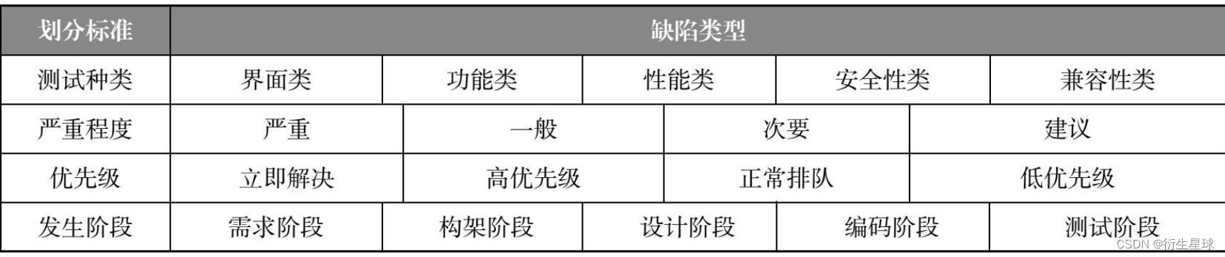
【软件测试】02 -- 软件缺陷管理
C语言数组专题训练
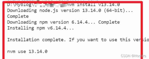
NVM Downloading npm version 6.7.0... Error
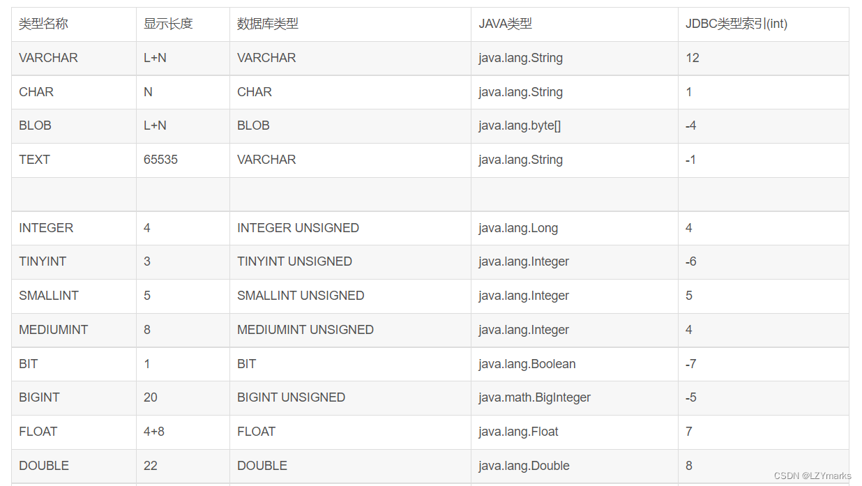
Database mysql all
Ros2 - configuration development environment (V)
. Net core stepping on the pit practice
【软件测试】04 -- 软件测试与软件开发
并发编程 — 如何中断/停止一个运行中的线程?
Orin installs CUDA environment
The “mode“ argument must be integer. Received an instance of Object
随机推荐
mingling
Error: “MountVolume.SetUp failed for volume pvc 故障处理
. Net core stepping on the pit practice
[Chongqing Guangdong education] National Open University 2018 autumn 0702-22t contemporary Chinese political system reference questions
In C language, int a= 'R'
Edge calculation data sorting
LSA Type Explanation - detailed explanation of lsa-2 (type II LSA network LSA) and lsa-3 (type III LSA network Summary LSA)
H5 embedded app adapts to dark mode
Special training of C language array
cgroup_ memcg
[tf] Unknown: Failed to get convolution algorithm. This is probably because cuDNN failed to initial
【MySQL8.0不支持表名大写-对应方案】
睿智的目标检测59——Pytorch Focal loss详解与在YoloV4当中的实现
LSA Type Explanation - lsa-5 (type 5 LSA - autonomous system external LSA) and lsa-4 (type 4 LSA - ASBR summary LSA) explanation
Integer to 8-bit binary explanation (including positive and negative numbers) scope of application -127~+127
Application of recyclerview
Initialization of global and static variables
Ros2 - first acquaintance with ros2 (I)
Error: "mountvolume.setup failed for volume PVC fault handling
Ros2 - ros2 vs. ros1 (II)