当前位置:网站首页>Blue Bridge Cup single chip microcomputer -- PWM pulse width modulation
Blue Bridge Cup single chip microcomputer -- PWM pulse width modulation
2022-07-05 03:21:00 【A lovely leather software】
One 、 principle
PWM The full name is Pulse width modulation (Pulse-width modulation), It is a way to reduce the average power transmitted by electrical signals by dispersing them into discrete forms . So according to Area equivalence The laws of , You can change the time width of the pulse by pair , In order to obtain the corresponding synthesis equivalently amplitude and frequency Waveform of .
The details are shown in the following figure :
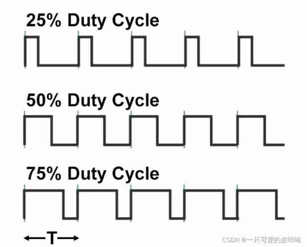
It can be seen from the above figure , Pulse width modulation Use a square wave whose pulse width will be modulated , And the average value of the wave pattern will change .
The average value of the wave pattern is obviously directly related to Duty cycle D of . There are three duty cycle states in the graph ,25%,50% and 75% Duty cycle status , It's not hard to find out , Assume that the duty cycle is D( It means in a pulse cycle , Proportion of power on time relative to total time Duty Ratio), Then meet : , among T yes PWM The cycle of , Usually the same period as the carrier .
utilize PWM control LED brightness :PWM It is a pulse width modulated signal , Among them “ Width ”, That is, the high-level time of the pulse .PWM Signal conditioning LED When the brightness is high , The signal frequency is constant , What changes is the time of the high level of the pulse , namely LED On time of . This kind of signal adjusting brightness is equivalent to adjusting LED The average current of , So the current will change .
Two 、 Programming
utilize PWM Pulse width signal realizes independent key pressing S7 Yes L1 Control of indicator light brightness change .
specific requirement :
1.PWM The frequency of the pulse width signal is 100Hz.
2. After the system is powered on L1 The indicator light is off .
3.L1 Indicator light yes 4 Two brightness modes , They are completely extinguished 、10% The brightness of 、50% The brightness and 90% The brightness of .
4. Press down S7 Key , Cycle switching L1 Four brightness modes of the indicator light .

First the J5 Jumper cap of 2 and 3 On the pin
#include <reg52.h>

sbit L1=P0^0;
sbit S7=P3^0;
unsigned	char count=0;
unsigned	char pwm=0;
void delay(unsigned int t)// The time delay function
{
 	while(t--);
}
void InitT0()// Timer initialization function
{
	 TMOD=0X01;
	 TH0=(65536-100)/256;
	 TL0=(65536-100)%256;

	 ET0=1;
	 EA=1;

}
void serviceT0() interrupt 1// Timer service function
{
    TH0=(65536-100)/256;
	 TL0=(65536-100)%256;// The timing of each interrupt is 100μs
	 count++;
	 if(count==pwm)
	 {
	  	L1=1;
	 }
	 else if(count==100)
	 {
	  	L1=0;
		count=0;
	 }
}
unsigned char flag=0;
void key()// Key related functions
{
	if(S7==0)
	{
	 delay(100);// Anti shake treatment
	 if(S7==0)
	 {
	 	  switch(flag)
		  {
		  	 case 0:L1=0;TR0=1;pwm=10;flag=1;break;
			 case 1:pwm=50;flag=2;break;
			 case 2:pwm=90;flag=3;break;
			 case 3:L1=1;TR0=0;flag=0;break;
		  }
		  while(S7==0);// Avoid touching by mistake
	 }
	}
}
void main()
{
	 P2=0xA0;P0=0x00;P2=0x80;P0=0xff;// Turn off the peripherals
     P2=0x80;L1=1;
	 InitT0();
	 while(1)
	 {
	  key();
	 }
}边栏推荐
- Linux Installation redis
- The latest blind box mall, which has been repaired very popular these days, has complete open source operation source code
- GFS distributed file system
- 001 chip test
- Kbp206-asemi rectifier bridge kbp206
- 单项框 复选框
- Why is this an undefined behavior- Why is this an undefined behavior?
- Sqoop installation
- Zabbix
- 2021 Li Hongyi machine learning (2): pytorch
猜你喜欢

this+闭包+作用域 面试题

Zabbix
Use of kubesphere configuration set (configmap)

看 TDengine 社区英雄线上发布会,听 TD Hero 聊开发者传奇故事
Hot knowledge of multithreading (I): introduction to ThreadLocal and underlying principles

Multi person online anonymous chat room / private chat room source code / support the creation of multiple chat rooms at the same time

Bumblebee: build, deliver, and run ebpf programs smoothly like silk

8. Commodity management - commodity classification

The perfect car for successful people: BMW X7! Superior performance, excellent comfort and safety

Simple use of devtools
随机推荐
Performance of calling delegates vs methods
[groovy] string (string type variable definition | character type variable definition)
Design and practice of kubernetes cluster and application monitoring scheme
Anchor free series network yolox source code line by line explanation Part 2 (a total of 10, ensure to explain line by line, after reading, you can change the network at will, not just as a participan
Sqoop命令
TCP security of network security foundation
Leetcode92. reverse linked list II
El select, El option drop-down selection box
Sqoop installation
El tree whether leaf node or not, the drop-down button is permanent
IPv6 experiment
Design of kindergarten real-time monitoring and control system
Comparison of advantages and disadvantages between platform entry and independent deployment
Daily question 2 12
The perfect car for successful people: BMW X7! Superior performance, excellent comfort and safety
Yyds dry goods inventory intelligent fan based on CC2530 design
001 chip test
The database and recharge are gone
Delphi read / write JSON format
[daily problem insight] Li Kou - the 280th weekly match (I really didn't know it could be so simple to solve other people's problems)