当前位置:网站首页>[Digital IC hand tearing code] Verilog edge detection circuit (rising edge, falling edge, double edge) | topic | principle | design | simulation
[Digital IC hand tearing code] Verilog edge detection circuit (rising edge, falling edge, double edge) | topic | principle | design | simulation
2022-07-05 01:41:00 【myhhhhhhhh】
Preface
This series aims to provide 100% Accurate numbers IC Design / Verify the title of the hand tearing code link , principle ,RTL Design ,Testbench And reference simulation waveform , The content of each article is checked by simulation . The quick navigation links are as follows :
Odd frequency division
Even frequency division
Semi integer batch
decimal / Fractional frequency division
Sequence detector
Mode three detector
Beverage machine
Asynchronous reset , Simultaneous release
Edge detection ( Rising edge , Falling edge , On both sides )
Full adder , Half adder
Gray code to binary
single bit Cross clock domain ( Two beats , Edge synchronization , Pulse synchronization )
Sync FIFO
Ought to say , The hand tearing code link is in the interview process Both important and simple A part of , Compared with software jobs , Numbers IC Hand tear code Fixed topic , Limited number , It belongs to a link that must be scored in the whole interview , Outside this series , I also recommend numbers IC Job seekers use “HdlBits” Code Training
Links are as follows
HDLBits — Verilog Practice
Edge detection circuit problem
1. Use Verilog Language , Design the rising edge detection circuit .
2. Use Verilog Language , Design the falling edge detection circuit .
3. Use Verilog Language , Design double edge detection circuit .
Principle of edge detection circuit
Here is to explain the principle , We need to analyze the characteristics of the edge circuit
For a rising edge circuit , If used clk Signals and registers are sampled , The previous shot was picked 0, The input result of the last beat is 1, Then through the operation of combinatorial logic , For the previous shot A Express , For the next shot B Express ,“!A & B” It is the rising edge detection we need .
Empathy , For the falling edge , The previous shot was taken 1, The input result of the last beat is 0,A&!B, It is the falling edge detection circuit we need .
For bilateral edges , The output is ** “!A & B + A&!B” **, namely A^B Exclusive or operation
The specific sequence diagram is as follows 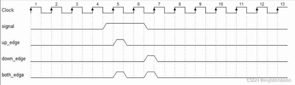
RTL Design
module edge_detect(clk,rst_n,signal,up_edge,down_edge,both_edge);

input clk;
input signal;
input rst_n;
output up_edge;
output down_edge;
output both_edge;

reg signal_r;

[email protected](posedge clk or negedge rst_n)
begin
if(!rst_n)
signal_r <= 1'b0;
else
signal_r <= signal;
end

assign up_edge   = !signal_r & signal;
assign down_edge = signal_r & !signal;
assign both_edge = signal_r  ^  signal;

endmodule
Testbench Design
`timescale 1ns / 1ps
module edge_detect_tb () ;

reg clk;
reg rst_n;
reg signal;

wire up_edge;
wire down_edge;
wire both_edge;

edge_detect u1(.clk(clk),
.rst_n(rst_n),
.signal(signal),
.up_edge(up_edge),
.down_edge(down_edge),
.both_edge(both_edge));

always #5 clk = !clk;

initial
begin
clk = 0;
rst_n = 1;
signal = 0;
#10
rst_n = 0;
#23
rst_n = 1;
#16
signal = 1;
#50
signal = 0;
#40
$stop;
end

endmodule
Result analysis

As shown in the figure, the rising and falling edges , Electric circuit output Edge arrival detected , Displayed in three wire type output On , The circuit design meets the expectation .
边栏推荐
- Is there a sudden failure on the line? How to make emergency diagnosis, troubleshooting and recovery
- Database postragesq PAM authentication
- WCF: expose unset read-only DataMember property- WCF: Exposing readonly DataMember properties without set?
- 线上故障突突突?如何紧急诊断、排查与恢复
- Five ways to query MySQL field comments!
- C basic knowledge review (Part 3 of 4)
- Roads and routes -- dfs+topsort+dijkstra+ mapping
- 微信小程序:星宿UI V1.5 wordpress系统资讯资源博客下载小程序微信QQ双端源码支持wordpress二级分类 加载动画优化
- Wechat applet: the latest WordPress black gold wallpaper wechat applet two open repair version source code download support traffic main revenue
- 如何搭建一支搞垮公司的技術團隊?
猜你喜欢

微信小程序;胡言乱语生成器

Async/await you can use it, but do you know how to deal with errors?
线上故障突突突?如何紧急诊断、排查与恢复
![[swagger]-swagger learning](/img/60/1dbe074b3c66687867192b0817b553.jpg)
[swagger]-swagger learning
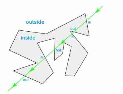
JS implementation determines whether the point is within the polygon range
One plus six brushes into Kali nethunter
Blue Bridge Cup Square filling (DFS backtracking)
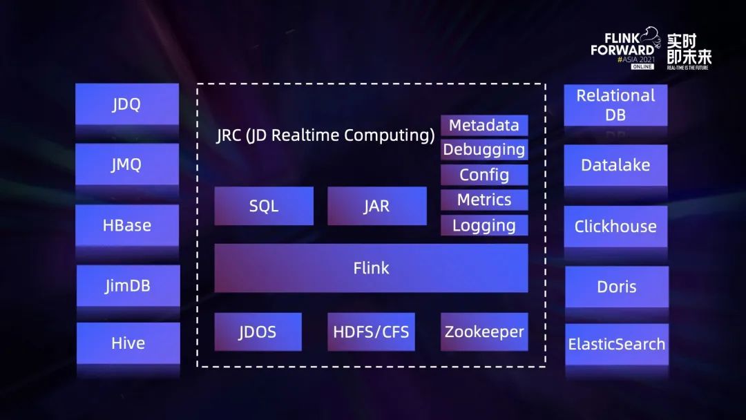
流批一体在京东的探索与实践

Wechat applet: new independent backstage Yuelao office one yuan dating blind box

如何搭建一支搞垮公司的技术团队?
随机推荐
Win:使用组策略启用和禁用 USB 驱动器
Common bit operation skills of C speech
Blue Bridge Cup Square filling (DFS backtracking)
Huawei machine test question: longest continuous subsequence
【大型电商项目开发】性能压测-优化-中间件对性能的影响-40
Do you know the eight signs of a team becoming agile?
微信小程序:独立后台带分销功能月老办事处交友盲盒
Redis' hyperloglog as a powerful tool for active user statistics
To sort out messy header files, I use include what you use
Interesting practice of robot programming 16 synchronous positioning and map building (SLAM)
Discrete mathematics: Main Normal Form (main disjunctive normal form, main conjunctive normal form)
Discrete mathematics: propositional symbolization of predicate logic
es使用collapseBuilder去重和只返回某个字段
Basic operation of database and table ----- the concept of index
如果消费互联网比喻成「湖泊」的话,产业互联网则是广阔的「海洋」
Mysql database | build master-slave instances of mysql-8.0 or above based on docker
Actual combat simulation │ JWT login authentication
phpstrom设置函数注释说明
Pytorch common code snippet collection
PHP wechat official account development