当前位置:网站首页>RGB LED infinite mirror controlled by Arduino
RGB LED infinite mirror controlled by Arduino
2022-07-05 06:01:00 【acktomas】
Arduino The control of the RGB LED Infinite mirror
2013 year 9 month 17 Daily update : Thank you Arduino competition Everyone who voted for this project in ( I am ten “ The second prize ” One of the winners )! If you want to use addressable LED Try this project with a light bar instead of a simulated light bar , Please check out Rainbow Jar project ( It's also Arduino The winner of the competition ).
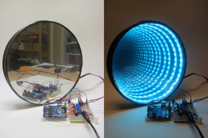
This is my combination of two classic projects : Use Arduino Of RGB LED Control and infinite mirrors . It's a RGB LED Infinite mirror , It allows you to switch between fading mode with adjustable speed and direct control mode , You can set red separately 、 Green and blue LED Brightness level . The main inspiration for this particular project comes from This infinite mirror Instructable and Adafruit Of RGB LED Light bar tutorial , But there are more high-quality resources in these two projects .
If you like , You can make a very simple 、 Cheap infinity mirror ( Just in Instructables Mid search “Infinity Mirror”, You will find some ), Or spend hundreds of dollars crazily ( If not thousands of dollars )( stay YouTube On the search “infinity mirror table”, You will understand ).
material : Electronic products,
2016 year 2 Monthly update :Jameco Electronics A kit containing all electronic materials for the project is now available . Please note that , This kit does not Include The material used to build the frame , So you still need to buy these materials separately ( See below ). As on this page Described at the bottom , I earn commission by selling this kit .
With mini breadboard and jumper Arduino UNO R3..
( Optional ):Arduino/ Bread board support . stay Thingiverse Found on This Cool simple design .
[1 rice RGB LED Light Bar .SparkFun With one Numbers RGB LED The lamp strip , The light bar has individually addressable LED( If you want to send one to the light bar at a time LED Light pulse , Or there are other modes ). Both strips can be cut to fit the length of your mirror .
four 10K Potentiometer .
Three N Ditch MOSFET.
22 AWG Connecting line ( black ). Like to use red and black respectively V+ Color code the ground connection . It can be downloaded from SparkFun get Smaller 25 Feet roll .
22 AWG Connecting line ( Red ). Same as the notes above , Scroll here smaller .
12V/5A DC power supply . I use RGB LED The light bar needs 12V, according to [ Data sheet ](https://www.sparkfun.com/datasheets/Components/LED/FLB6 5060RGB(300) Waterproof FLEX STRIP.pdf), Every 3-LED paragraph ( The smallest unit that the light bar can be cut into ) Consume 60mA. therefore , In the whole lamp with 60 individual LED when , The absolute maximum value under full brightness is 1.2A. I have one 12V The charger .
Adafruit and SparkFun Both have smaller 、 Cheaper 12V Power Supply ( Respectively 1A and 600mA), According to the size of the mirror and how many it will use LED, It may well meet your needs .
material : Build a mirror
important : Building this mirror requires three main parts : Ordinary mirror 、 Frame and one-way mirror . First , If you can find a cardboard / A pulp cover and an ordinary mirror that fits snugly inside , That's the simplest —— The parts I bought don't fit together perfectly , So I have to use a solution ( See step 6). secondly , According to the tools available to you , Cutting acrylic can be painful , So please plan accordingly ( See step 9 and 10).
About LED There is another important consideration for the light bar , It cannot be cut to any length - It must be cut into 3-LED Multiple of segment , The length is less than 2 Inch - So you want Inside perimeter Your frame is a multiple of that length . therefore , I will link to the components I use to build the mirror , But you can still follow these instructions to build mirrors of different sizes or shapes .
- 9" Diameter round mirror . I bought this set [7 A mirror , The aim is to make some smaller infinite mirrors .
- 8 Inch 、9 Inches and 10 Inch diameter circular carton . important Yes. - I bought these in the hope 9 An inch diameter mirror can cling to 9 Inch lid or inside the box itself ( Because I can't ’ You can't find a separate box for sale on Amazon ). It has no .9" The lid of is too small , and 10" Your box is too big . therefore , I put 9" The top of the lid was cut off . , And only use rims . If you skip and view page 6 Picture in step , This will make sense . The key is , Ideally , You should use a mirror close to the pulp cover or box .
- 1/8" thick 12"x12" Transparent acrylic ( organic glass ) plate . Available for purchase . If you can use a laser cutting machine , Acrylic is very easy to cut . I don't have , So I try to use puzzles ( The first 9 Step ) And scoring ( The first 10 Step ). Both work quite well , But it will cause some jagged edges , In hindsight , rectangular Mirrors are better than round mirrors . If you want to make a slightly smaller mirror ,McMaster sell Pre cut 6" Diameter circle . I didn't shop around for bigger pre cut circles , But you may find them .
- Mirror window film . I order from Amazon [ These things .
- Black paint . I bought a can of ordinary black spray paint .
- Optional : If you want to be very fancy , You can order a custom size one-way mirror , Instead of sticking the window reflective film on a piece of plexiglass . This may provide you with higher optical quality in your final product .
Tools
- Soldering iron . I have a [ One from SparkFun Variable temperature .SparkFun The product page says “ You need to weld on your own wire .” But when my strip arrived, all four wires had been welded . even so , take ( Stranding ) Pushing the end of the line into the bread board can be painful , Therefore, I suggest welding on small solid wires to make it easier .
- Lead free solder .
- Wire stripper , If you don't have a pair to peel 22 AWG Wire stripper . Again , if necessary , You can squeeze through without these , But I bet most people who read this article have wire cutters .
- Mini needle nose pliers , If you are as clumsy as I am and hate to handle tiny bread board components with your fingers .
- Electric drill ( See the first 6 Step —— You may only need a sharp knife to escape )
- seccotine
- Electrical tape
See? ? It's time to start building !
The first 1 Step : How infinite mirrors work ?

Okay , almost It's time to start building . First , I want to pre empt another common comment : How these things actually work ?
Not surprisingly , There is no magic . The secret is , The infinity mirror actually contains two different transmissivity and Reflectance mirror . For all practical intentions and purposes , The mirrors we deal with in our daily life are 100% The reflection of the ( Technically speaking , A small amount of light will also Absorbed , But we can ignore this for the time being ). This is an infinite mirror “ Back ” Regular mirror ( On the left side of the above figure ). However , Colored window film ( On the right side of the figure above ) Only about half of the light is reflected *. It means , When you will LED Caught between two mirrors , some Light will escape through the front mirror and enter your eyes . The rest bounce back from the rearview mirror , Then enter the front mirror again , This process continues to infinity - Hence the name . however , Because a little light escapes every time , Every continuous illusion you see LED It looks a little darker , Until they gradually disappear - you actually You can't see infinite LED.
Please note that , this It doesn't work , Because the window tone “ Only light is allowed to pass in one direction ”, This is a common misunderstanding . In order to make the illusion work properly , The side of the front mirror where the observer is ( The outside world ) Must have LED One side of ( Infinite mirror ) Much darker . This is with you in the crime drama / The effect seen in the movie is the same , Someone was locked up in an interrogation room , There is a mirror on the wall , But someone on the other side of the mirror observed , It seems that it is just a window . Only when the interrogation room is well lit , When the observation room is dark , this only It works .
* Reflectivity / The exact percentage of transmittance may vary depending on the type of product you purchase - Different levels of reflectivity and transmittance are actually regulated in different states , For windows , If you are curious , Please Google .
Add tips, questions, comments, downloads
step 2: Build the circuit

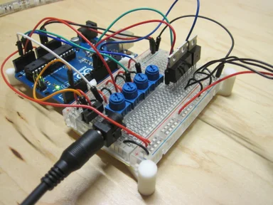
Before building the image , It's best to build 、 Test and debug the circuit . otherwise , If you get a beautiful , Fancy mirrors are just to throw away the switch and find something doesn't work , That would be very sad . therefore , First let's assemble the circuit and test LED Light Bar . If you are not familiar with the circuit and do not understand what happened , You can (a) Follow the instructions blindly , perhaps (b) Look forward to the next step to explain the working principle of the circuit .
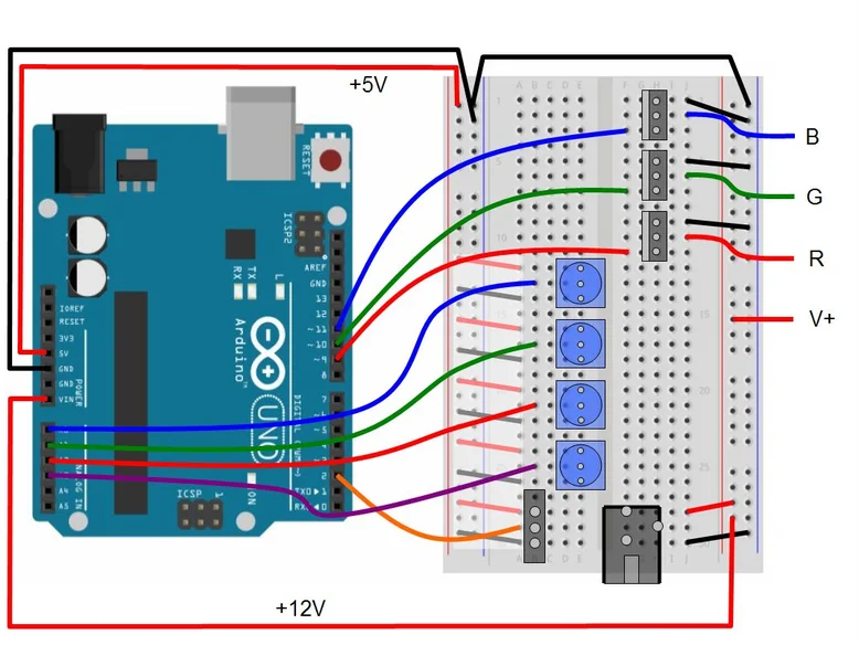
If you have experience in using test boards , Then the circuit can be assembled according to the third test board diagram above or directly from the circuit diagram . For novice , I divide it into three steps , Hope to make things less overwhelming - Corresponding to the first three charts above :
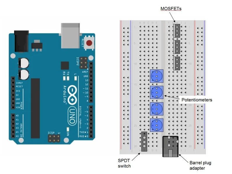
1) With three MOSFET, Four potentiometers ,SPDT Switch and barrel jack adapter fill bread board . I make these parts in the above figure “ transparent ”, So that you can see exactly the position of their pins *.
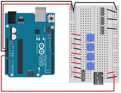
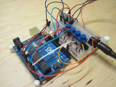
2) Add wires to connect to the power and ground rails . Here I color code these with red and black , But remember , If you only have a multicolor patch cord kit and no red and black connectors , You can use any color you want . Please note that *, One of them How to connect the guide rail of the test board from the barrel Jack to +12V Power Supply ( adopt Vin Feed the power supply to Arduino), The other is connected to Arduino Of +5V Power pin , But they share one Common ground *. Whatever you do , Do not short circuit at the same time +12V and +5V Power Supply !
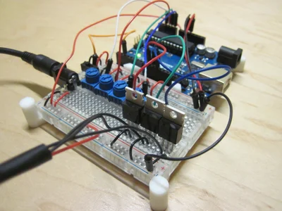
3) Add wires to connect to Arduino Input and output of , And to connect to LED Wire of light bar ( If your light strip has pre welded wires , Please use these wires )**. Again , I'm here for their respective red , Green and blue wires are color coded , But your ability to do this will depend on the wires available .
* I started in Fritzing Make this picture in , But yes MOSFET And potentiometers and other components are frustrated by the large amount of space they occupy in the breadboard view mode ( They provide quasi 3D View instead of “ From top to bottom ” View , So it takes up much more space than in real life , And cover up other things on the bread board ). therefore , I intercepted Arduino Screenshot of bread board , And in Powerpoint They are drawn in .
** If your LED The light strip does have pre welded wires , Please be careful with the color coding .SparkFun The product page of indicates , The blue and green wires are switched , This can be annoying , But it won't cause any harm . My light belt has a connection to V + Of black Line , stay LED Reversing polarity on the light strip may be bad news . I think I understand that I don't want to use two red lines ( One for V+, One for red LED), But I hope they use something other than black to express V +.
Add tips, questions, comments, downloads
step 3: How the circuit works ?
This is a rough explanation of how the circuit works and the purpose of the component . Experienced people can skip this step , But if you're curious , Please read on . I don't have time to write a whole introductory chapter on circuits , So I try to provide relevant links when possible .
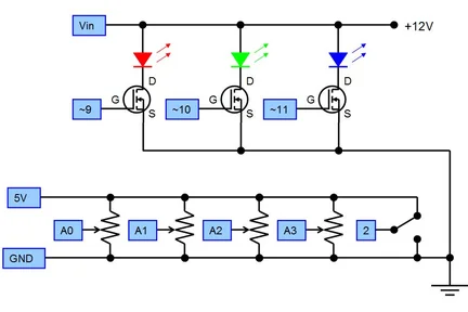
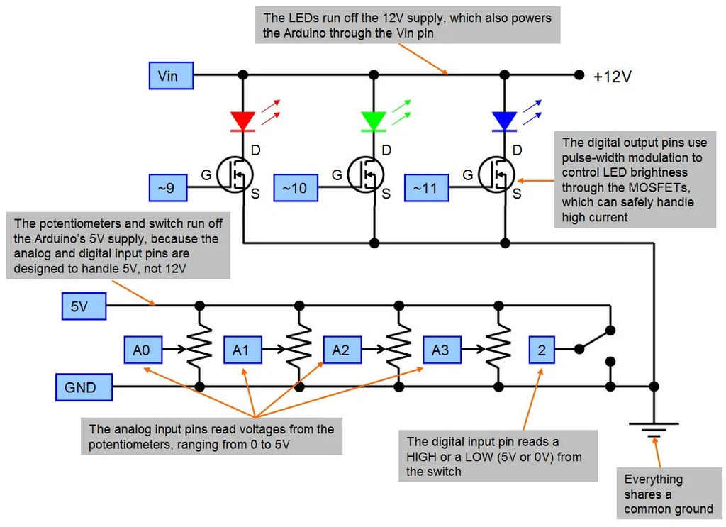
Barrel jack adapter Provide +12V Power Supply . This is for LED Necessary for power supply of light bar , And also through its Vin Pin for Arduino Power supply *.* Technically speaking ,Arduino The built-in barrel plug of will accept +12V Power Supply , Then you can go through Vin Pin accesses the power supply , however LED It will consume a lot of current - More than you want to pass Arduino Current of board operation . such , The current will “ split ”——Arduino Only absorb what it needs , The high current enters directly through the test board LED. Special thanks Adafruit Support Forum Help me solve this problem .
SPDT switch Just a switch , Used to select where the program is located “ Pattern ”. The details of the code will be explained in the next step , But in essence, it is only rotating through different colors “ fade ” Switch between mode and direct control mode , You can control a single red , Green and blue LED brightness . The middle pin of the switch is connected to Arduino One of the digital input pins of , Two external pins are connected to +5V And ground . therefore , According to the turning mode of the switch , Program usage digitalRead() Function read Numbers High or low and work accordingly ( Be careful :SPDT representative “ SPDT ”, Wikipedia page about switches There is a good form , Different types of switches are summarized , With charts ).
** Potentiometer ** It's you “ control ” Of , It depends on which mode the program is in . In independent control mode , Three potentiometers control red 、 Green and blue LED The brightness of . In fade mode , A single potentiometer controls the rate of fading . The potentiometer has three pins . Same as switch , One pin is connected to +5V, One pin is connected to ground . However , Different from the switch , Rotating the potentiometer will make the voltage on the middle pin be 0V and 5V Between continuity change , Not just switching between the two . therefore , The middle pin of the potentiometer is connected to Arduino Of simulation Input . then , Use analogRead() function ,Arduino Convert this voltage into 0 To 1023 Number between , In order to use ( Please refer to the next step ).
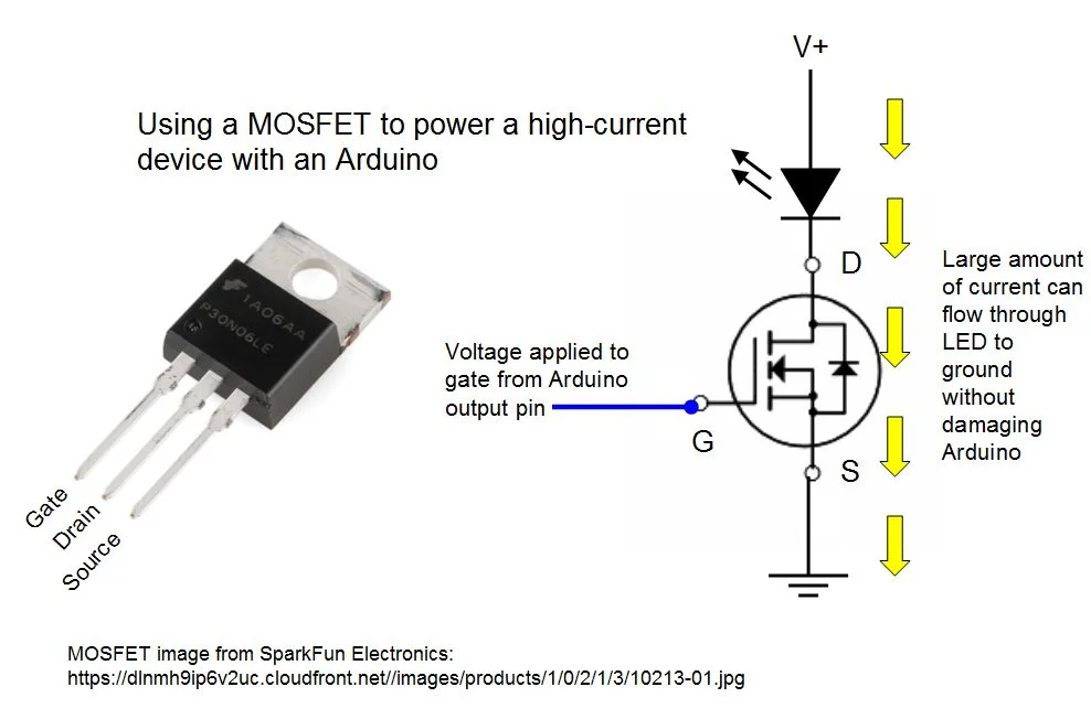
MOSFET It may be the hardest part for beginners in electronics to understand . These are the drivers “ high power ” equipment ( Such as motor , Solenoids and LED Light Bar ) Necessary , These devices usually need to be better than Arduino The current that can be provided is more current . On Wikipedia The pages about these are actually quite dense , So I will try to give a simplified explanation here .MOSFET There are three pins , be called “ Grid ”(G)、“ Drain electrode ”(D) and “ Source pole ”(S). In the simplest form ,MOSFET Like a valve , Let the current flow from the drain to the source .“ gate ” Control this valve ( Think about opening and closing a valve into the garden hose ), Except that control is electric Not mechanical . from Arduino The voltage applied to the gate by an output pin of the makes MOSFET“ open ” - Allow high current to flow from drain to source , No need Actual from Arduino Absorb any current . If from Arduino The voltage to the grid is zero ,MOSFET Will turn off and block the current flow . In this way , You can use a small Arduino Control huge motors and lights , As long as you have an external power supply large enough to handle it .
I should also mention Pulse width modulation (PWM). This is a method for using Arduino control LED Common techniques of brightness . In short ,Arduino The output pin of is Numbers Of , Therefore, they can only output high level or low level (5V or 0V). They cannot be adjusted by continuously changing the voltage LED Brightness or motor speed . contrary , What they can do is send out very fast pulses (Arduino About per second 500 Time ), Much faster than human eyes can see . Each pulse consists of a HIGH Paragraph and a LOW Section composition , The relative ratio between the two determines what we actually see “ brightness ”.0% Gao He 100% Low pulses look like “ close ”.100% Gao He 0% Low will be “ Full brightness ”,50% high /50% Low will be about half brightness . You see. . In this circuit ,PWM The signal is sent to MOSFET, then MOSFET Control passed LED High current of , So as to achieve “ Decline ” Effect and adjustable brightness .
step 4:Arduino Code
The following Arduino Copy and paste the code into the new sketch . I won't write my own tutorial here , So if you don't know how to create / Upload sketches , Please check the official Arduino - introduction page .
Be careful : This may not be the most effective code ! especially , I'm not sure if there is a better way to continuously monitor the fading rate potentiometer , Instead of copying and pasting the same line of code over and over again , Or if there is a way to break through when turning the switch for loop ( Now? , If you switch to personal control mode in fade mode , Before completing the current fade in and fade out cycle , No switching ). therefore , I'll throw it there , As a challenge to anyone who is reading this article and wants to release better code . obviously , I am essentially a mechanical engineer , Not a programmer .
// Arduino code to control and RGB LED strip
// Uses a toggle switch to switch between color-fade mode
// and individual RGB control mode
// adapted from http://learn.adafruit.com/rgb-led-strips/example-code

const int RED = 9;    // define digital output pins for individual red,
const int GREEN = 10;  //green and blue channels
const int BLUE = 11;


const int POT1 = 0;    // define analog input pins for three potentiometers
const int POT2 = 1;
const int POT3 = 2;
const int POT4 = 3;

const int BUTTON = 2;  // define digital input pin for the switch

int val = 0; // stores the state of the switch input pin

int FADESPEED = 0;  // initiate fade speed set by potentiometer

int r = 0;  // initialize the red, green and blue values

int g = 0;

int b = 0;

void setup() {
  pinMode(RED, OUTPUT);    // define digital pins as outputs and inputs as needed
  pinMode(GREEN, OUTPUT);
  pinMode(BLUE, OUTPUT);
  pinMode(BUTTON, INPUT);
}

void loop() {
  val = digitalRead(BUTTON);   // read the input value from the toggle switch

  if (val == HIGH) {
    // code for RGB color fade
    /**
      By starting from the  4  A potentiometer reads the analog input to set the fade in and fade out speed
     analogRead  A value between  0  and  1023  Number between , And in milliseconds “ Delay ”,
      So the maximum delay you will get here is about 1/10  second . Divide by different numbers to change the maximum fade in and fade out time .
    */
    FADESPEED = analogRead(POT4) / 10; // set the fade speed by reading analog input from 4th potentiometer
    // analogRead will output a number between 0 and 1023, and "delay"
    // is in milliseconds, so the biggest delay you'll get here is about
    // 1/10 of a second. Divide by a different number to change the max
    // fade time.
    // fade from blue to violet
    for (r = 0; r < 256; r++) {
      analogWrite(RED, r);
      /**
        Keep checking the fade in and fade out speed , otherwise ,  It will not be updated until a complete cycle is completed . Maybe not the most effective way ...
      FADESPEED = analogRead(POT4) / 10; // check the fade speed continuously, otherwise
      // it won't update until it's gone through a complete cycle.
      // Probably not the most efficient way to do this...
      delay(FADESPEED);
    }
    // fade from violet to red
    for (b = 255; b > 0; b--) {
      analogWrite(BLUE, b);
      FADESPEED = analogRead(POT4) / 10;
      delay(FADESPEED);
    }
    // fade from red to yellow
    for (g = 0; g < 256; g++) {
      analogWrite(GREEN, g);
      FADESPEED = analogRead(POT4) / 10;
      delay(FADESPEED);
    }
    // fade from yellow to green
    for (r = 255; r > 0; r--) {
      analogWrite(RED, r);
      FADESPEED = analogRead(POT4) / 10;
      delay(FADESPEED);
    }
    // fade from green to teal
    for (b = 0; b < 256; b++) {
      analogWrite(BLUE, b);
      FADESPEED = analogRead(POT4) / 10;
      delay(FADESPEED);
    }
    // fade from teal to blue
    for (g = 255; g > 0; g--) {
      analogWrite(GREEN, g);
      FADESPEED = analogRead(POT4) / 10;
      delay(FADESPEED);
    }
  }
  else {
    // code for individual RGB control with potentiometers
    r = analogRead(POT3) / 4; // read values from the 3 potentiometers and divide by 4 to set brightness
    g = analogRead(POT2) / 4; // note that analog read is 10-bit (0-1023), analog write is an 8-bit PWM
    b = analogRead(POT1) / 4; // signal so you need to divide this value by 4.

    analogWrite(RED, r);     // write analog values to red, green and blue output pins
    analogWrite(GREEN, g);
    analogWrite(BLUE, b);
  }

}
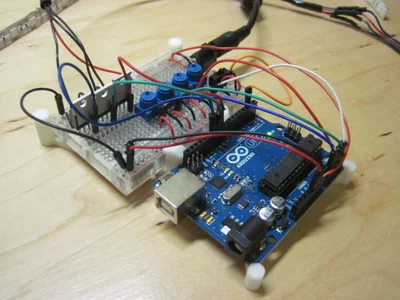
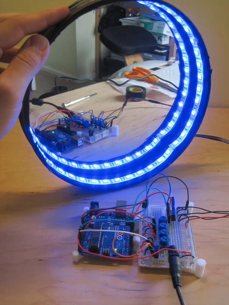
step 5: Test circuit 、 Code and LED Lamp with
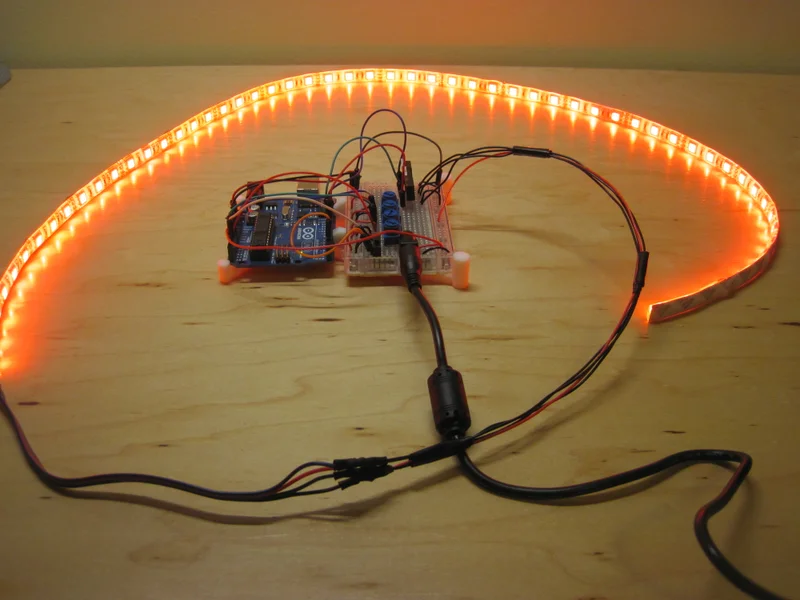
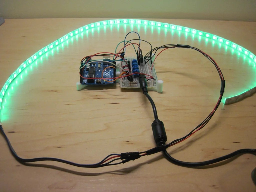
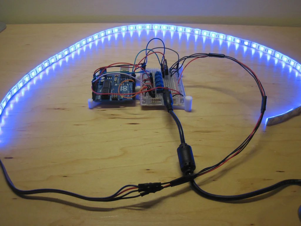
Plug the power supply into the barrel jack adapter , stay Arduino It takes a second to start , You should be able to control the light ! Use the toggle switch to switch between the two modes . In one mode , You can use the first three potentiometers to directly control red 、 green 、 LAN San Road LED brightness ; And combine them to make different colors . In another mode ,LED Will fade automatically between colors , But you can use the fourth potentiometer to control the fading rate .
Watch this video to demonstrate , If it doesn't work , Please refer to the troubleshooting tips below . Please note that , There are several places in this video , my LED flashing - This must mean when I put Arduino When pushing around , I have a loose connection or two exposed wires collide with each other somewhere . watch out .
Troubleshooting tips
- Check your test board connection . Just a wire placed in the wrong position can stop the whole thing from working .
- Ensure that I/O The pin matches the pin actually used . If you copy and paste my code directly , This should not be a problem , But there is no harm in checking .
- Make sure your LED The light bar works normally . take LED Light bar V+ The wire is directly connected to the... On the test board +12V Power rail , Then insert the respective wires into the ground rail , Test red 、 Green and blue .LED The lamp strip has a built-in resistor , So you don't have to worry about blowing it out . If each color lights up , Then your light bar is ok , And the problem lies elsewhere in the circuit .
- Use routine LED Test circuits and codes **, skip MOSFET**. If MOSFET A little too new and confusing , You can make an introductory version of this project , Use only three ordinary old LED, Or a RGB LED( Search for SparkFun or Adafruit And other common suppliers , There are many options ). These are low current and low voltage , Enough to make them directly from Arduino drive , Unwanted MOSFET, however You will need a current limiting resistor , In order to LED It won't burn .LED Flickering and fading are very common starts Arduino project , So I won't reproduce the direction here .
- Skip potentiometer , Use hard coded color pattern to test the circuit . This allows you to ensure PWM Signals and MOSFET Normal work , Don't worry about analog inputs and potentiometers .
You may have noticed a trend here - The general idea is to put your circuit ( Or code ) Decompose into smaller ones that can be tested separately , Isolated part . This allows you to narrow down , Search for problems in a partitioned way , Instead of just staring at a huge circuit and messy code , Want to know what's wrong .
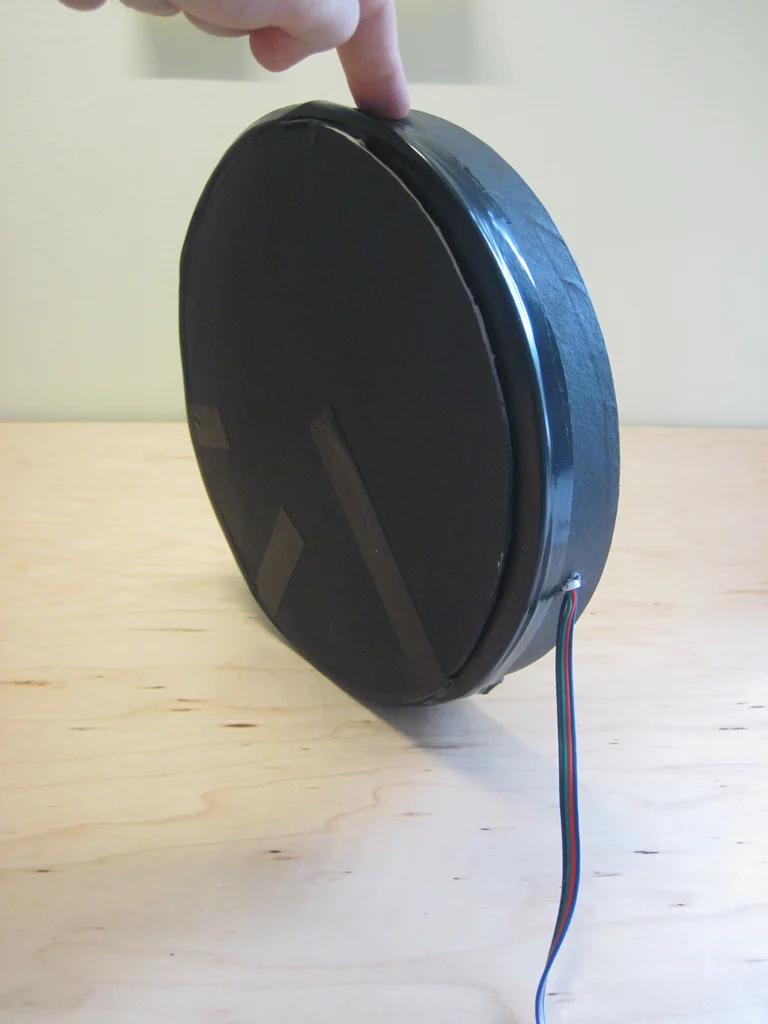
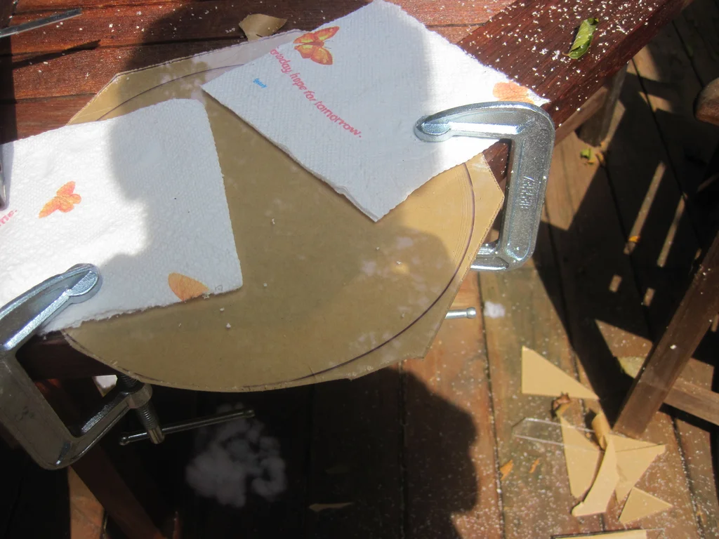
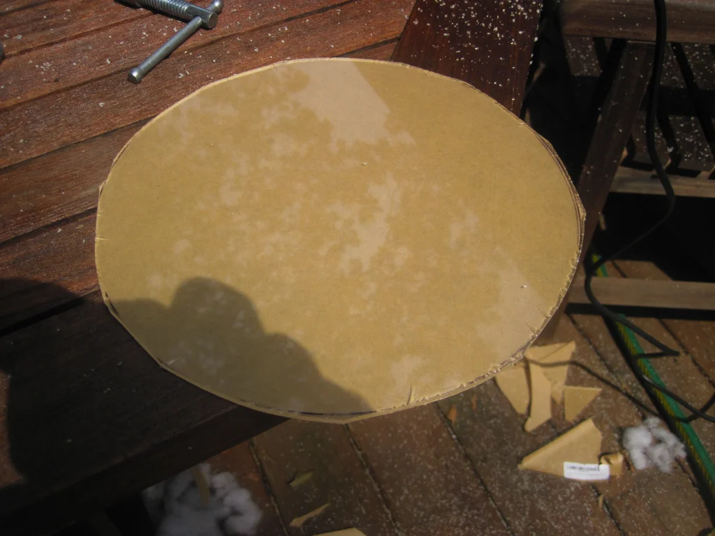
step 6: Prepare the frame
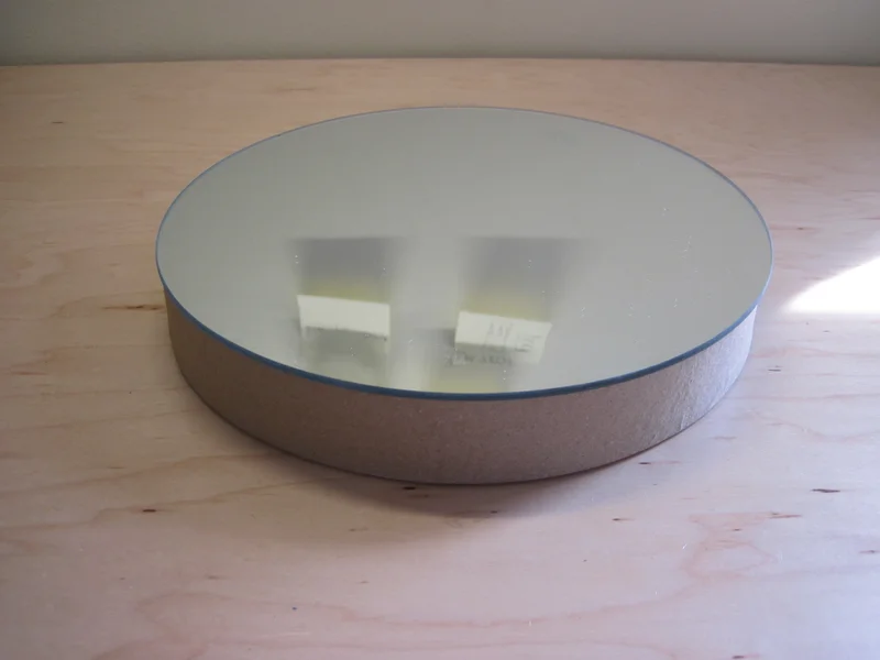
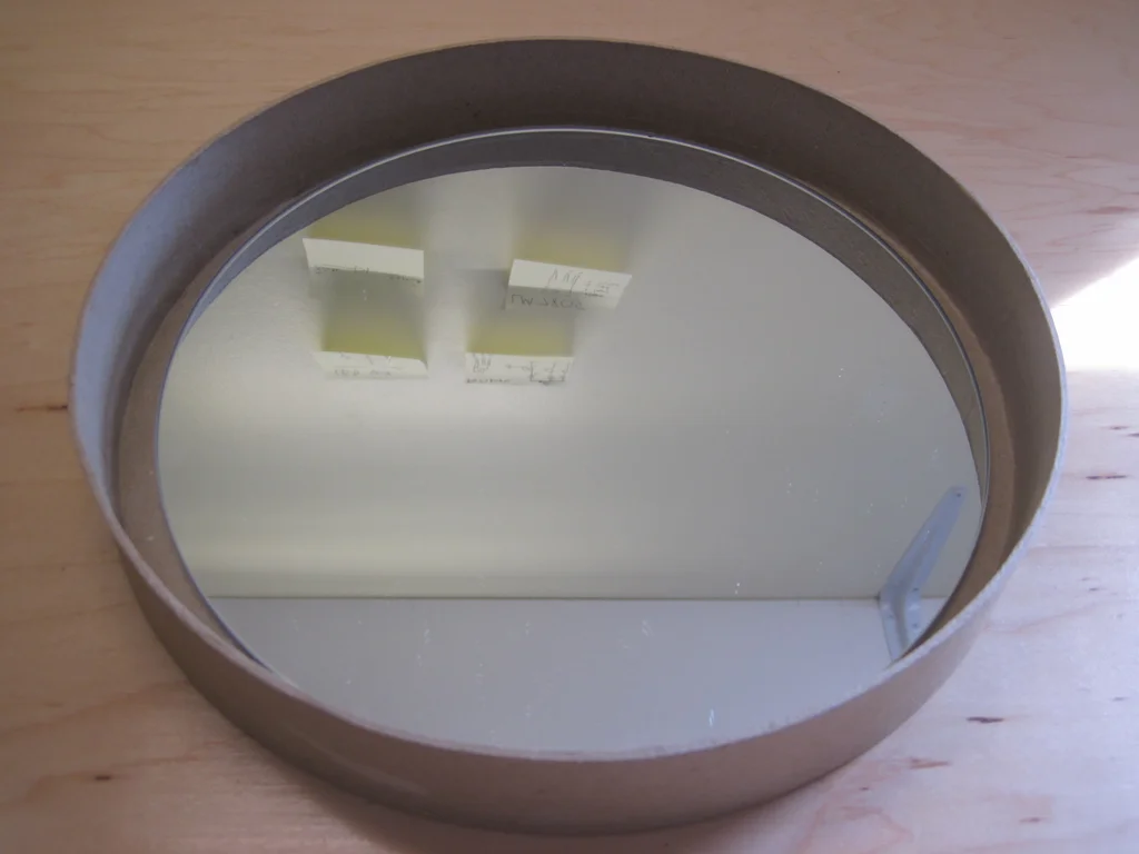
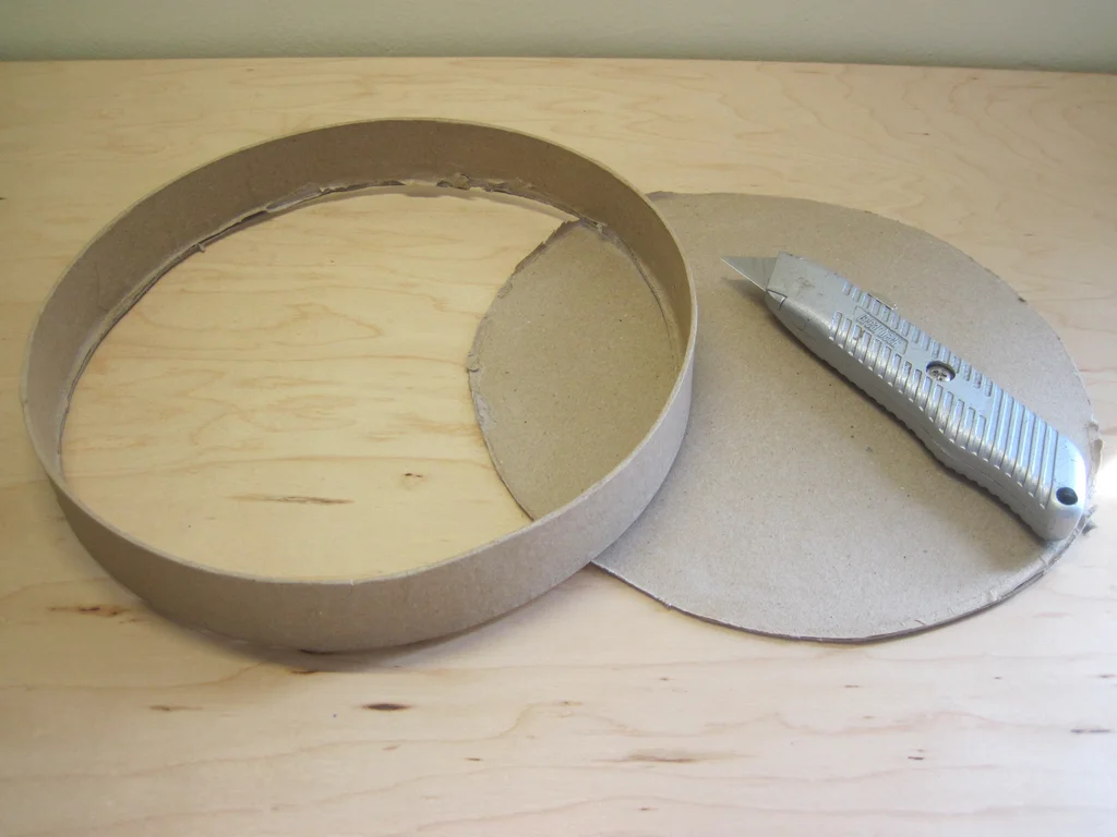
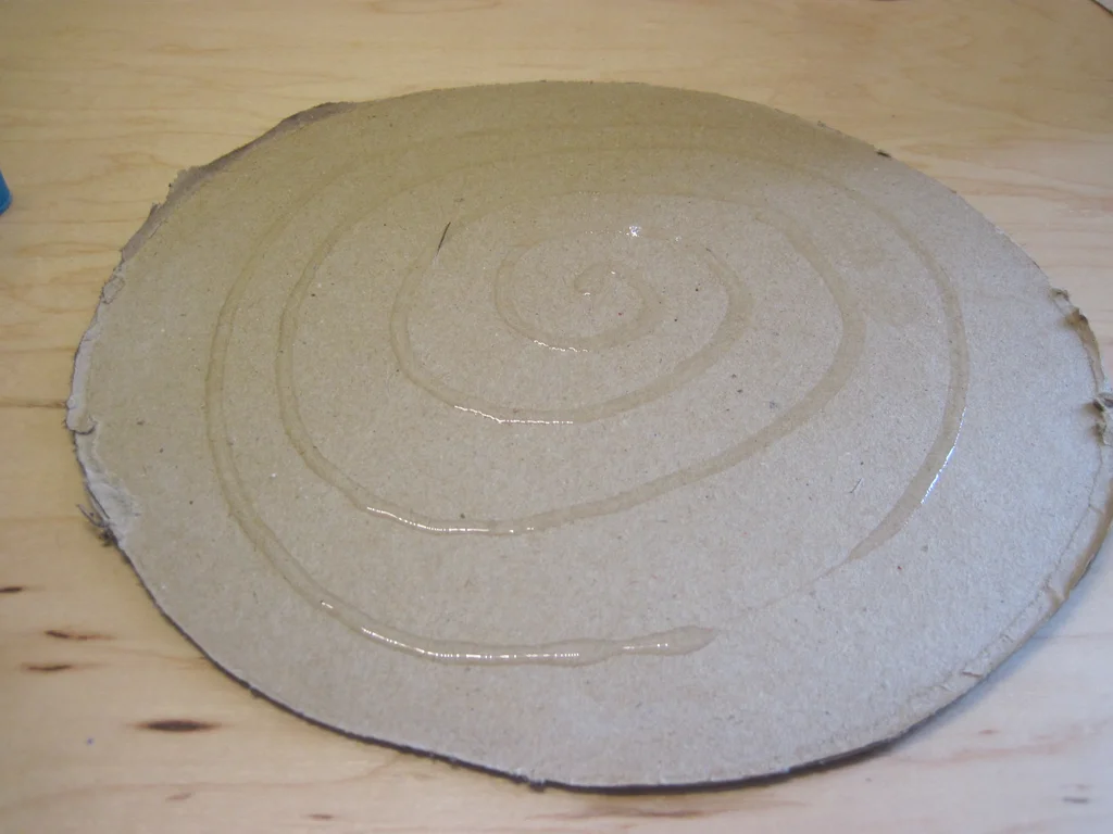
therefore , I am what I am hope my 9 Inch diameter mirror can cling to me 9 Inch diameter lid or box itself . It can be seen from the picture above ,10 Inch diameter boxes and lids are too big . My solution is to cut 9 Inch cap top , Then use only cylinders . I kept the round part cut from the top , To strengthen the back of the mirror . therefore :
1) Carefully cut off the top of the cardboard cover with a knife .
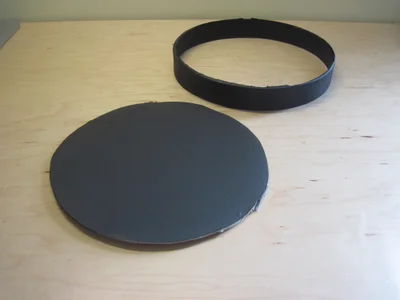
2) Paint the two pieces with the color you choose . I believe if the inside of the edge is black , Then the vision will be better , External is not important .
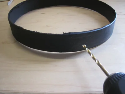
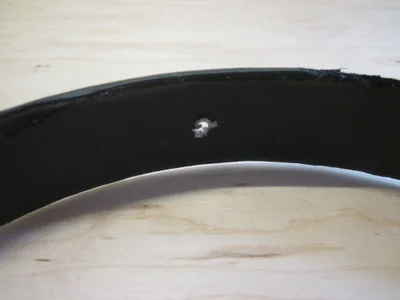
3) Drill a large enough hole on the side of the contour , send LED The wires on the lamp belt can pass through . In hindsight , I should drill first , Then draw .
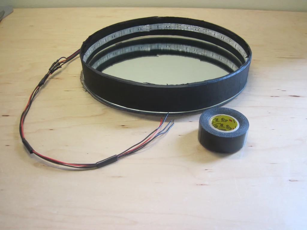
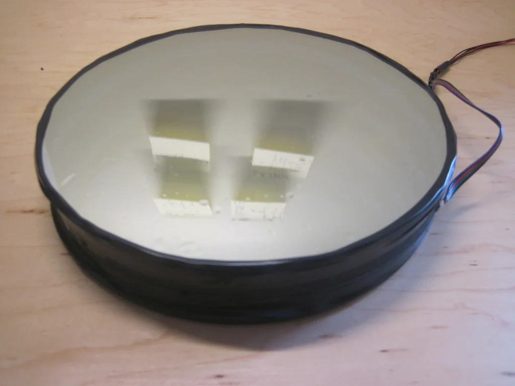
step 7: install LED Light Bar
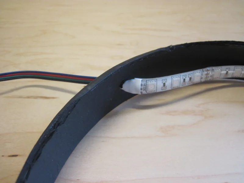
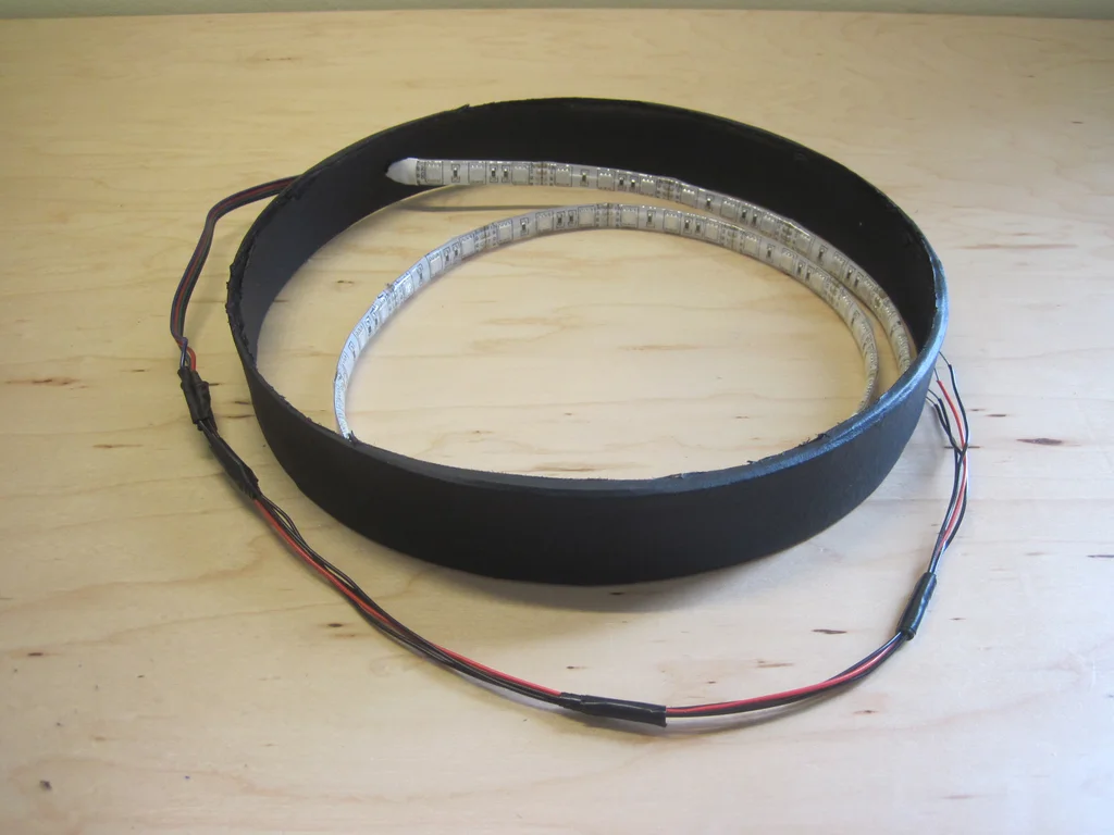
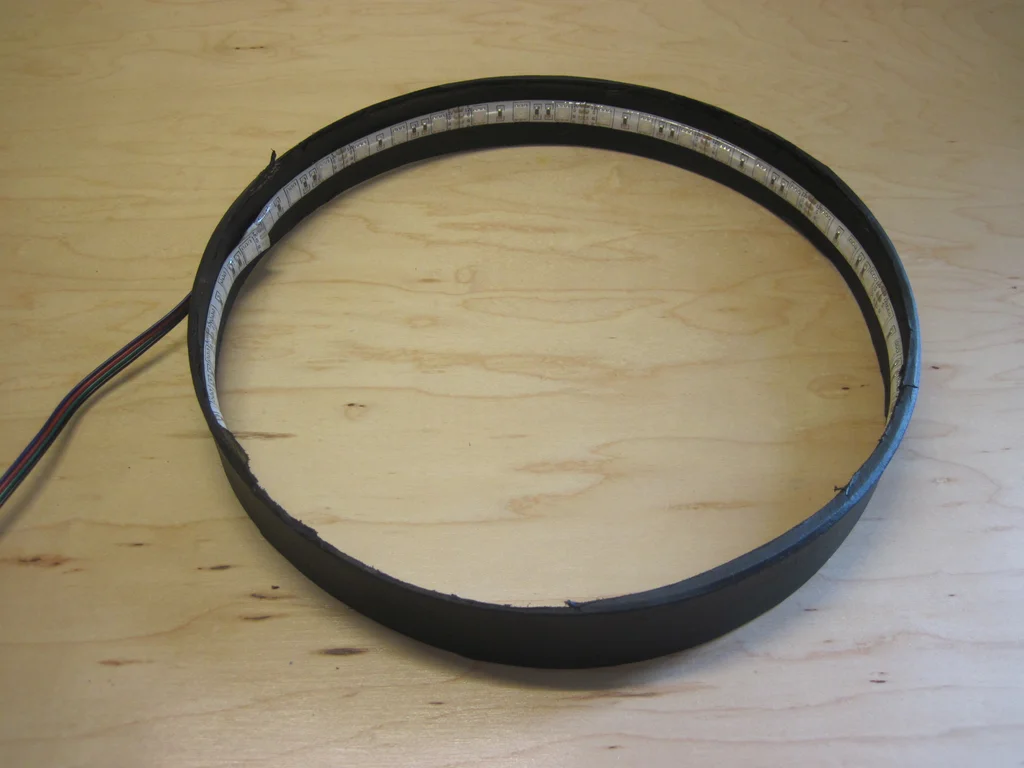
take LED The light ribbon goes through the hole you drilled in the cardboard cover .
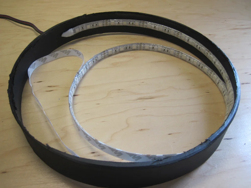
Start carefully from LED Remove the adhesive tape backing from the light strip , Then press it firmly on the inside or on the cover . Make sure it is centered in the cylinder .
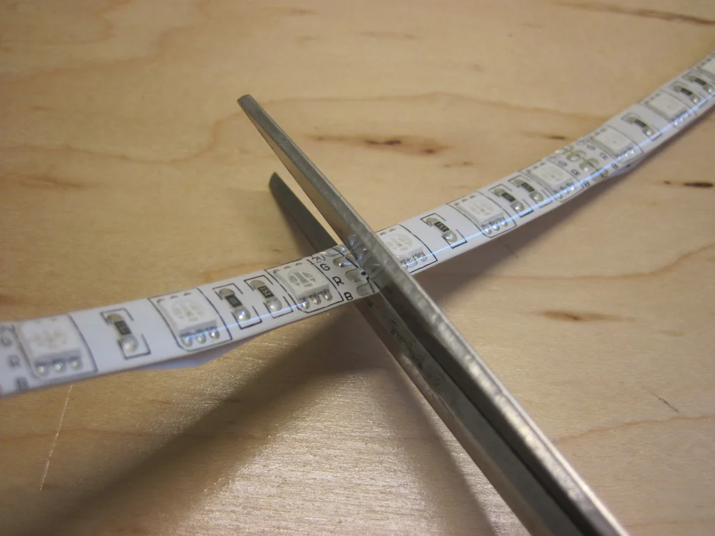
Once you have completely determined the length of the light band , Just cut it off LED Lamp with . Important note :LED You can't just cut anywhere - You must cut it into 3 individual LED paragraph , And you can see the cutting line with the marking pad . If you cut anywhere else , Then the last few of the light bar LED Will not work properly .
You must also want the perimeter of the cover to match these 3-LED Multiple of segment length ( about 1 15/16) Well matched , Otherwise you may be in the first and last LED There is a gap or a little overlap between .
step 8: Assemble the frame
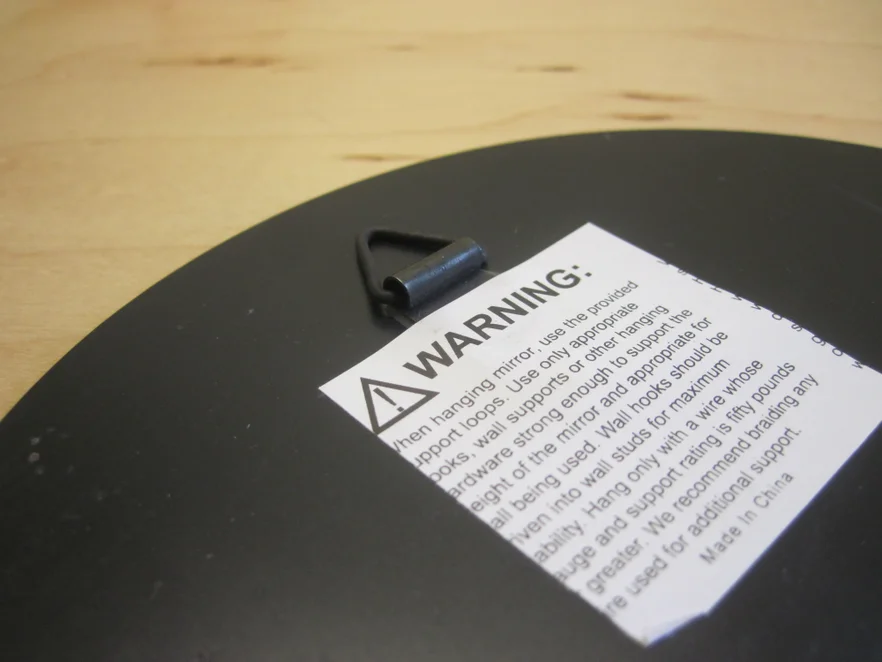
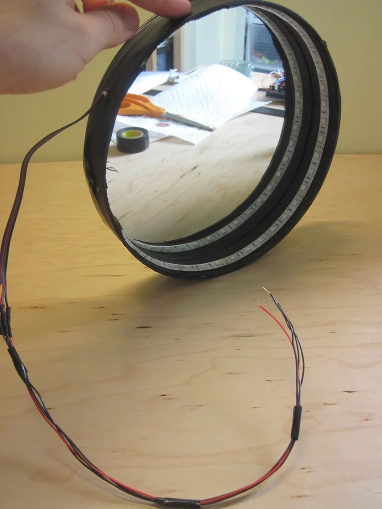
There are small hooks on the back of the mirror I bought , When I take it off the package 9 Inch mirror , I accidentally pulled the hook off the package . therefore , It could be a good thing , I didn't try to hang it on the wall with it . in any case , This can be solved , because You need to Take off the hook , So that the mirror can be placed flat inside the frame .
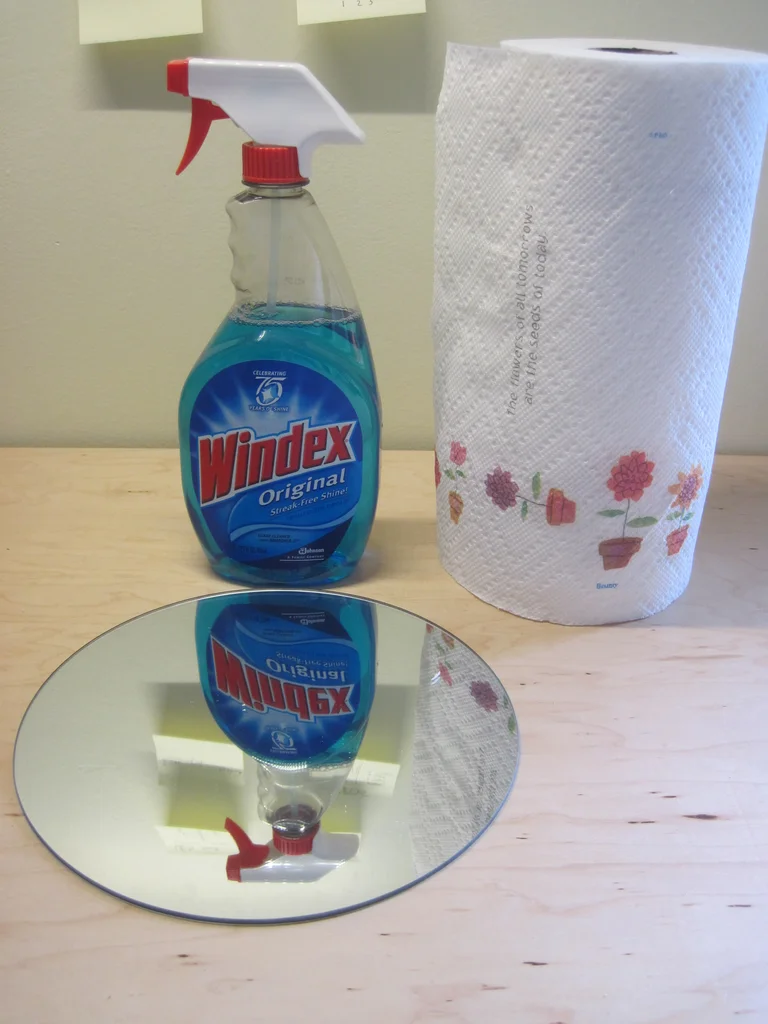
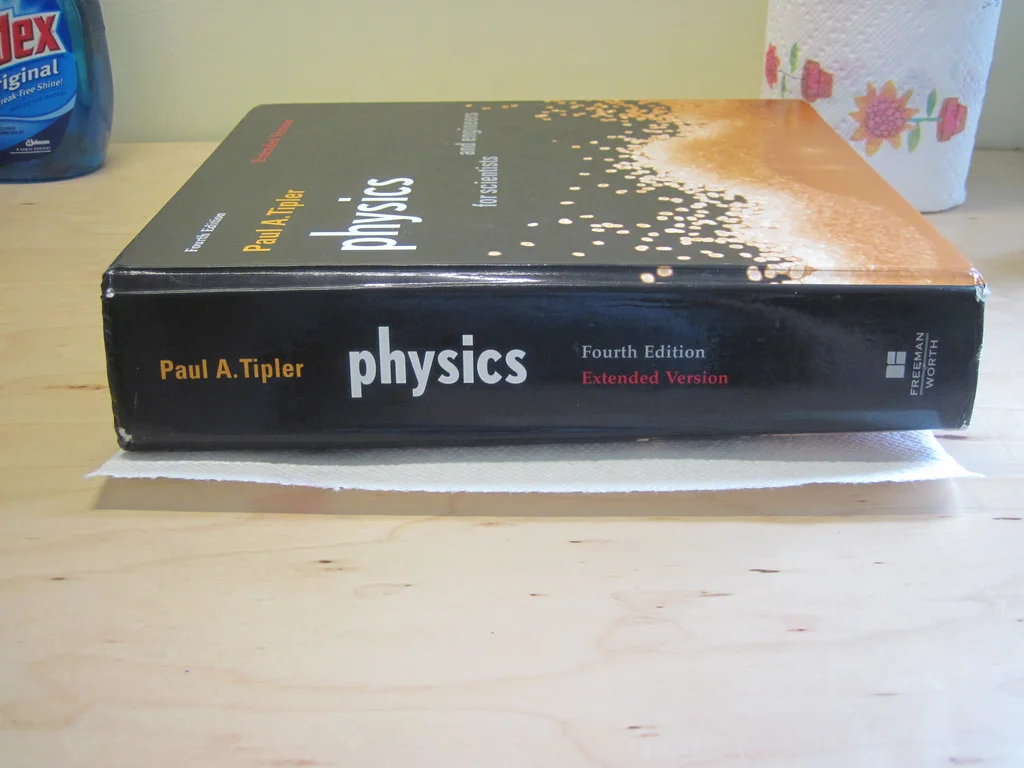
I used to glue the back of the mirror to the flat of the cardboard cover ( Not painted ) part . Now may be a good time to make sure your mirror is clean and free of fingerprint stains , Because any defect will diminish the illusion in the finished product . From then on , I use paper towels to deal with / Pick up the mirror , To avoid leaving extra fingerprints around the edges .
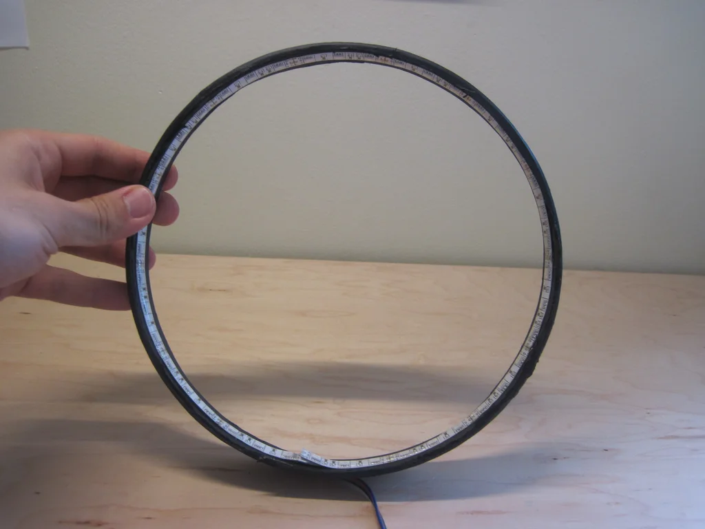
Stick the mirror on the cardboard circle , I just use electrical tape LED The light strip is wrapped around the outer edge of the rim , And connect it to the mirror ( Of course , Tape can also , But I hope it's black ). Again , This is just a circuitous process that I have to go through , Because my mirror didn't fit the lid at the beginning .
Once you have everything safe , start-up Arduino And ensure that it is not damaged in some way in this process LED Light strips or wires may be a good idea .
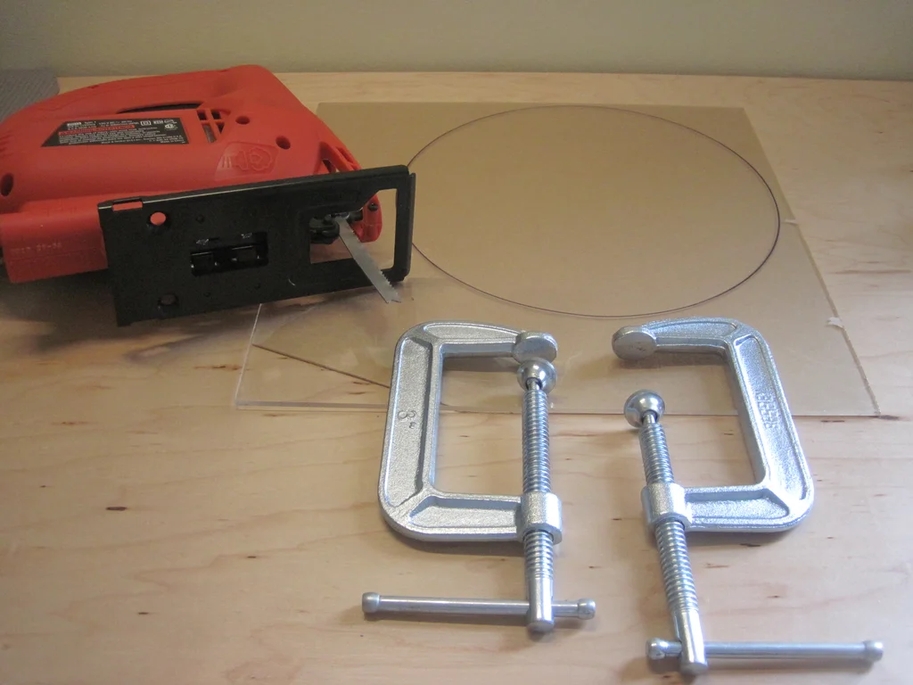
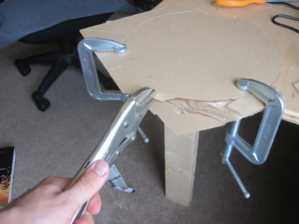
step 9: Cutting acrylic - Puzzle
Thank you for your participation To this forum post The idea of people .
Continue with the previous important safety information : If you use a laser , Acrylic smoke is bad for you . If you are cutting / Sawing / polishing / Whatever , You don't want to breathe dust . Make sure to work in a well ventilated place , And wear appropriate masks when necessary .
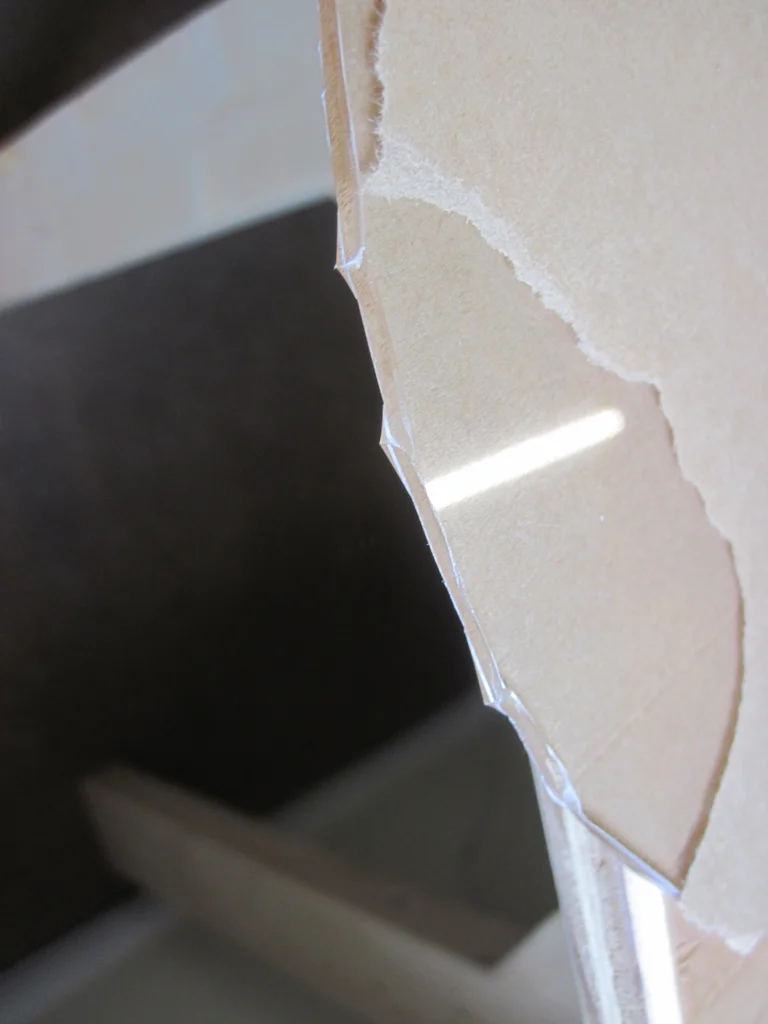
therefore , Through the puzzle : I will 9 The outline of the inch mirror is traced on the acrylic paper backing . then , I use two C Type a clip secures it to the edge of the table , Then roughly cut off the corners , Make an octagon . then , I made smaller cuts continuously along this line . The end result is not Too much too bad - There are some cracks around the edge , But there is no catastrophic fracture to destroy the circle .
Some safety precautions - First I tried this with a wooden blade , It doesn't work at all , Cause some big , The serrated acrylic sheet breaks when the blade is stuck . Bought a thinner metal blade at the hardware store , The effect is much better . The edges are still sharp , So I just polish them by hand to avoid cutting . As usual , Electric tool , I suggest using safety glasses to complete this step .
Add tips, questions, comments, downloads
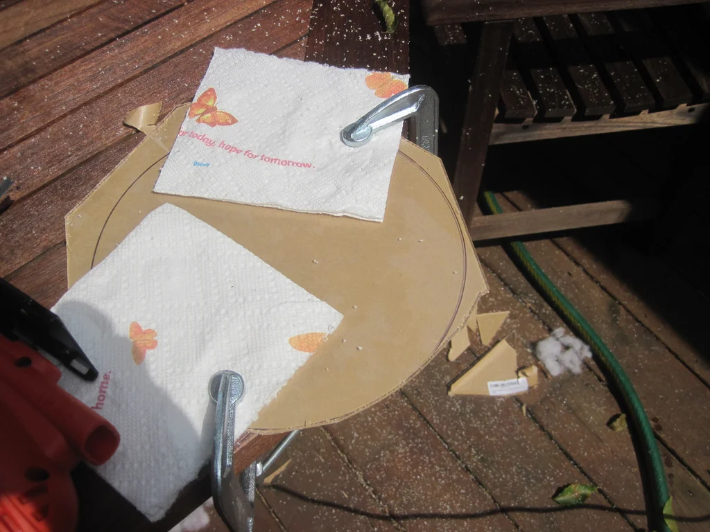
step 10: Cutting acrylic - Scratch and catch
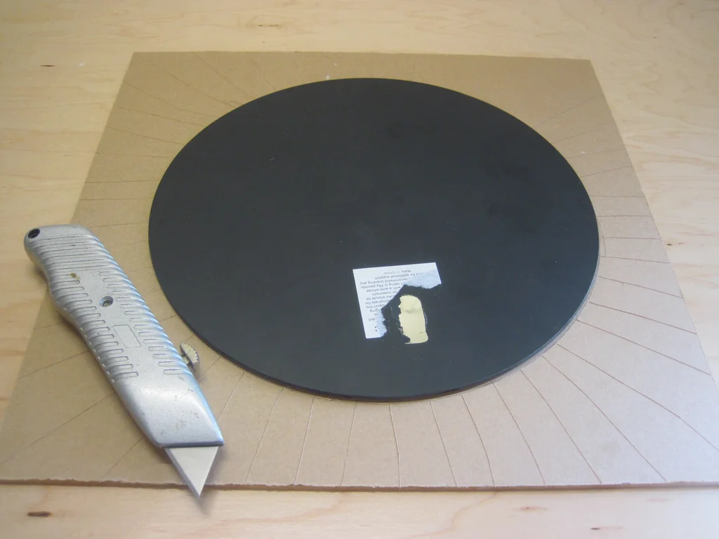
Another way I cut acrylic acid is to draw a circular outline with an art knife , Then draw a bunch of additional radial lines , I hope I can break a single fragment , Finally, leave a circle in the middle .
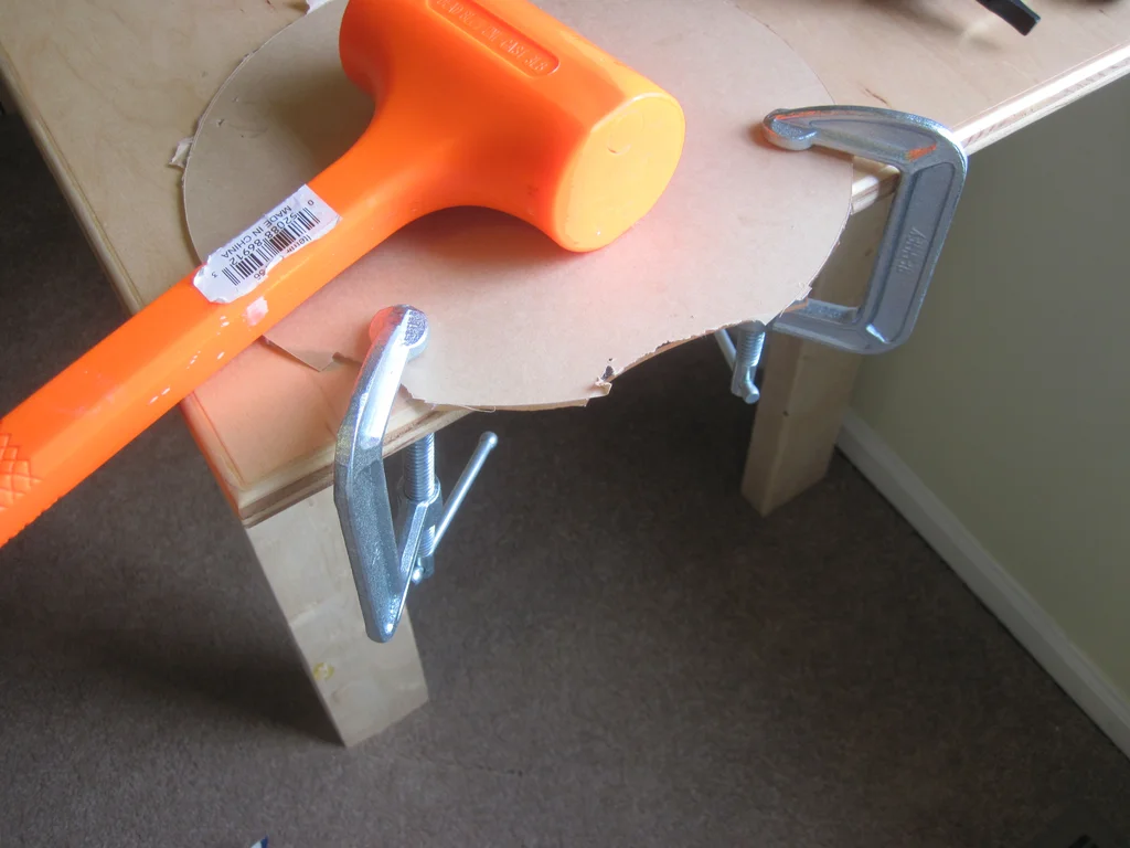
I First of all Try this for the first time , I use C Type a clip clamps acrylic on the edge of the table , Then hit the separated fragments with a mallet . It doesn't work , Cause the block to break within the circumference of the circle ( however , If you are making a rectangular mirror , This is good for straight cutting ).
Next , I started from Forum post Got some useful suggestions : I rated acrylic acid , Then put it in the refrigerator for a few hours *.* Then I use... Again C Clip , But hold the edge with a vise and break , Instead of hitting it with a mallet . It works very well , There are fewer cracks around the edges than the jigsaw method . It still has some sharp points sticking out , I polish it down .
To be fair , I have never tried to use a vise clamp without freezing first , Or use a mallet after freezing - So I can't 100% Determine whether the vise clamp or freezing makes it work better for the second time .
Add tips, questions, comments, downloads
step 11: Apply mirror tone
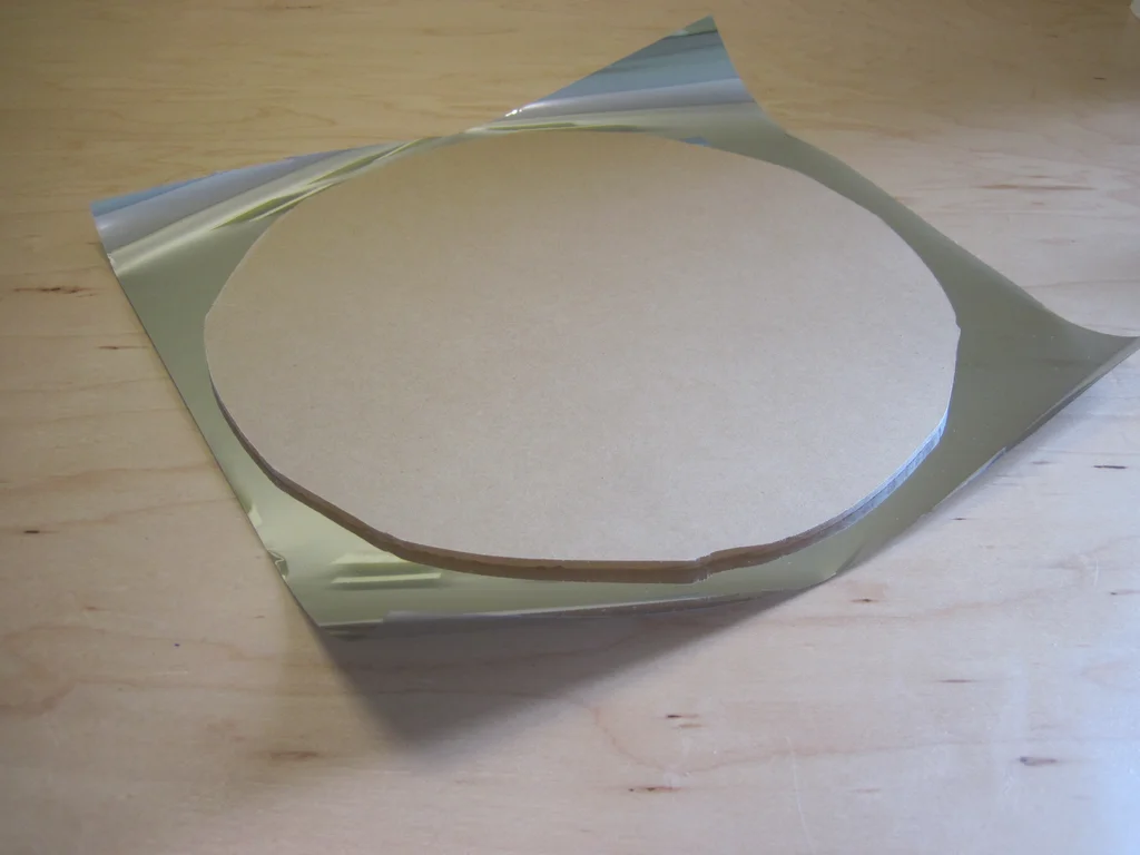
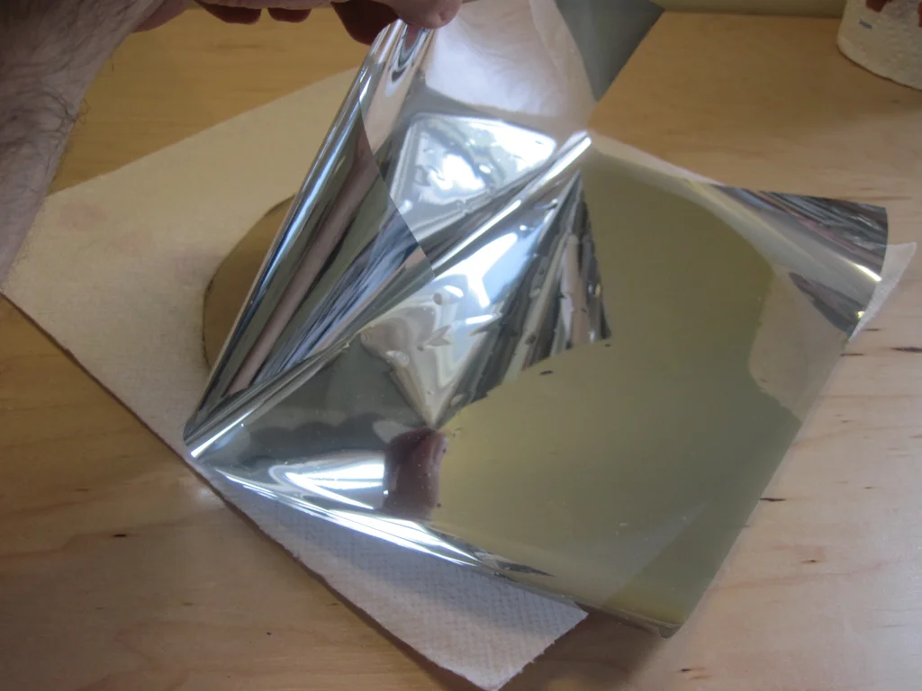
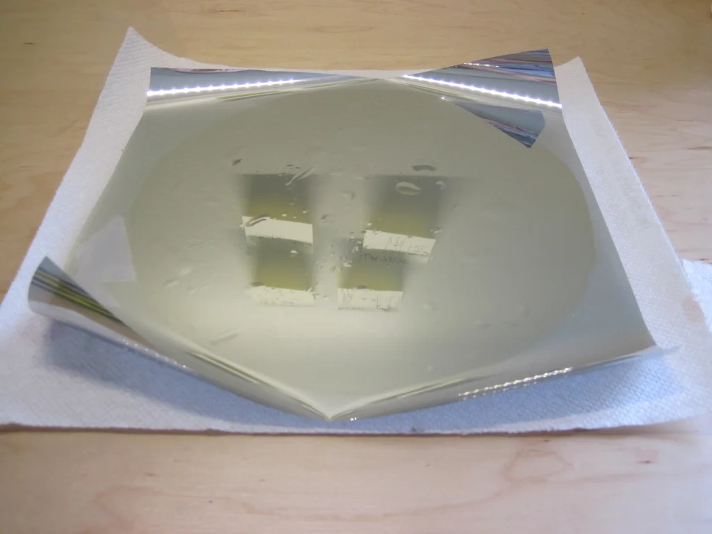
At this point , We assume that you have somehow managed to cut the acrylic into the right size . Before proceeding , Please make sure to wipe / Clean acrylic ( Fingerprint stains , Grinding dust, etc ).
Next , You need to cut a piece more than acrylic Bigger Mirror tone - This means that you can deal with extra material on the edges , Don't worry about fingerprint stains .
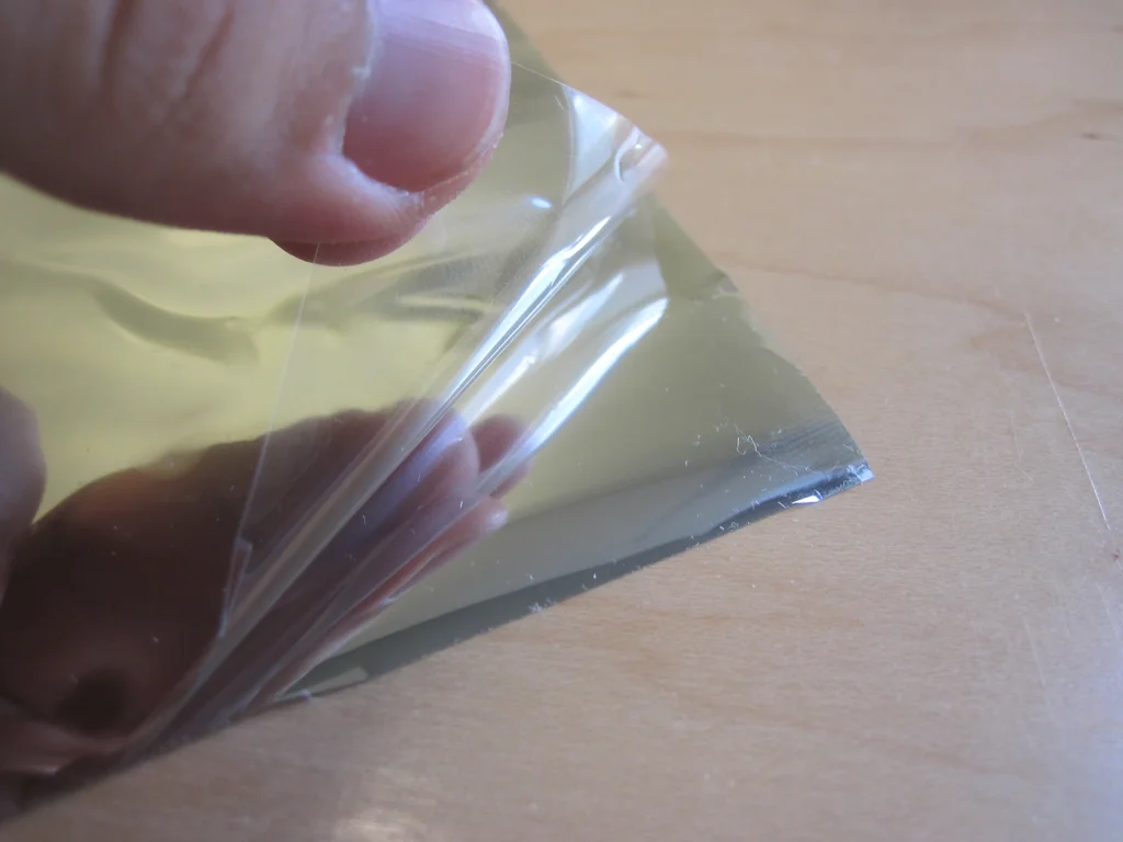
The tinted side of the window has a transparent protective coating , You need to remove it to expose the adhesive . Start at the corner , Carefully peel off the transparent layer with your nails ( This can be painful ), then Carefully Put the mirror tone flat on your acrylic . I think this is the most frustrating part of the whole project / The hardest part - You want to make the hue as flat as possible , There are no bubbles . Big bubbles will be painfully visible in the last mirror , And may detract from hallucinations . I try my best to make the tone as flat as possible , And push them towards the outer edge with your fingertips ( Use paper towels , So I won't stain the color of the window ) Come on “ eject ” Some bubbles . If you really screw up the first time you try , You can strip most of the hue of the window , Then try to lay it flat , The adhesive should not lose its stickiness . If all the other methods fail , You can also cut only one piece of new work .
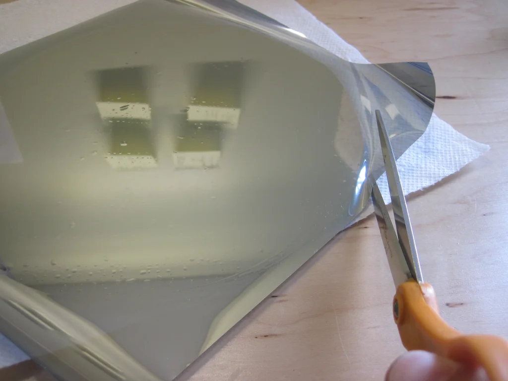
Once you are satisfied with the appearance and smoothness of the window color , Cut the periphery with scissors , So it will be equal to your acrylic .
step 12: Connect the unidirectional mirror to the frame
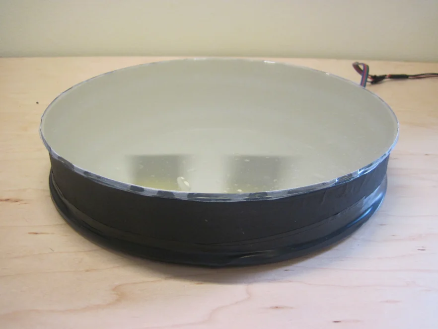
There's nothing to see here … Place a unidirectional mirror , The mirror tone is towards * towards *.* I just used electrical tape around the outer edge again . If you want to be more fancy , You can install the one-way mirror on the inside of a slightly larger cardboard cover , Then put it outside the frame .
* ad locum , I just follow the instructions I see on other infinity mirrors . In optics , It should work in either direction , As in step 1 Described in . Maybe acrylic is just harder to scratch / Easier to clean , So it's best to let it face outward … honestly , I'm not sure .
Add tips, questions, comments, downloads
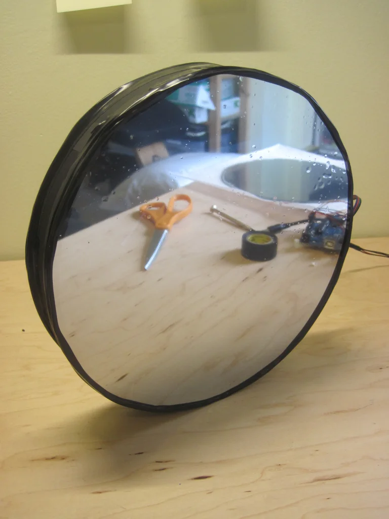
step 13: Light it up !
Plug in the power and start it ! Suppose you are in step 5 In the test LED Light Bar , And there are no major problems in building mirrors , Then it should work as advertised . The above is a bunch of photos I took under different lighting conditions ( The darker the room ,“ Infinite ” The better the result. ), Here is the video of the final product .
I want beginners to understand this as clearly as possible Inscipleable - So if you see something unclear , Or I skip / It implies what you think should be spelled out , Please leave a comment and let me know .
边栏推荐
- Simple knapsack, queue and stack with deque
- Sword finger offer 53 - I. find the number I in the sorted array
- Detailed explanation of expression (csp-j 2021 expr) topic
- Sword finger offer 53 - ii Missing numbers from 0 to n-1
- Sword finger offer 05 Replace spaces
- Sword finger offer 05 Replace spaces
- 【实战技能】如何做好技术培训?
- Cluster script of data warehouse project
- Fried chicken nuggets and fifa22
- A misunderstanding about the console window
猜你喜欢
![[practical skills] technical management of managers with non-technical background](/img/4d/1081c71df6ee2087359111baf7498a.png)
[practical skills] technical management of managers with non-technical background

【Jailhouse 文章】Look Mum, no VM Exits

【实战技能】如何做好技术培训?
Arduino 控制的 RGB LED 无限镜
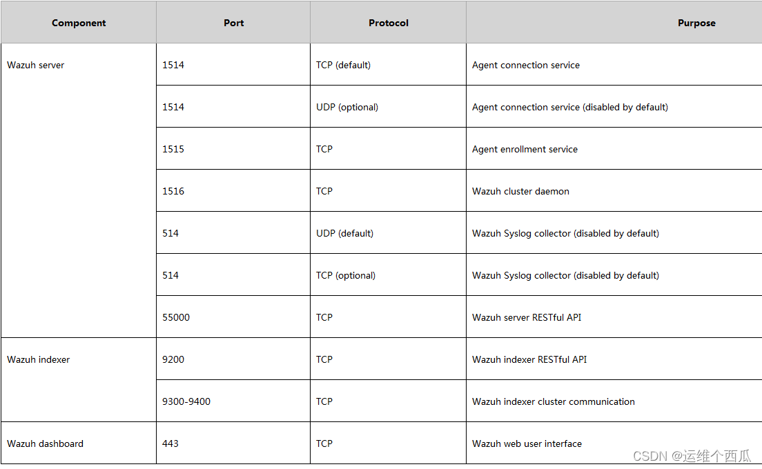
Introduction and experience of wazuh open source host security solution

AtCoder Grand Contest 013 E - Placing Squares
Implement an iterative stack

中职网络安全技能竞赛——广西区赛中间件渗透测试教程文章

CCPC Weihai 2021m eight hundred and ten thousand nine hundred and seventy-five
The connection and solution between the shortest Hamilton path and the traveling salesman problem
随机推荐
数据可视化图表总结(二)
Daily question 1688 Number of matches in the competition
全排列的代码 (递归写法)
【Rust 笔记】16-输入与输出(上)
Simply sort out the types of sockets
LeetCode 0108.将有序数组转换为二叉搜索树 - 数组中值为根,中值左右分别为左右子树
中职网络安全技能竞赛——广西区赛中间件渗透测试教程文章
Solution to the palindrome string (Luogu p5041 haoi2009)
6. Logistic model
[practical skills] how to do a good job in technical training?
【Jailhouse 文章】Look Mum, no VM Exits
Sword finger offer 04 Search in two-dimensional array
每日一题-无重复字符的最长子串
Codeforces Round #715 (Div. 2) D. Binary Literature
剑指 Offer 35.复杂链表的复制
常见的最优化方法
剑指 Offer 05. 替换空格
Educational codeforces round 109 (rated for Div. 2) C. robot collisions D. armchairs
【Rust 笔记】17-并发(下)
884. Uncommon words in two sentences