当前位置:网站首页>3D laser slam: time synchronization of livox lidar hardware
3D laser slam: time synchronization of livox lidar hardware
2022-07-07 02:14:00 【The moon shines on the silver sea like a dragon】
3D laser SLAM:Livox Lidar hardware time synchronization
Preface
In progress robot slam Often, a single sensor cannot achieve strong robustness , Many times, the fusion of multiple sensors is needed , For example, lidar + The camera +IMU+GPS+ Wheel speedometer + Millimeter wave radar and so on .
In the process of multi-sensor fusion, it involves the correspondence of data frames , If you need to use a timestamp to correspond , Then time synchronization is required . Due to different degrees of delay in the transmission and reception of data , The frequency of data generation is also different , If you only use soft synchronization , Then there must be some deviation , Resulting in inaccurate data alignment , Then it reflects the importance of hardware time synchronization .
This article mainly introduces in 3D laser SLAM in , How to Livox Lidar time hardware synchronization .
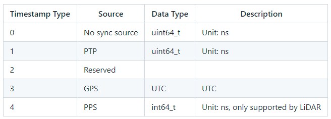
Livox Device support 3 Time synchronization :
- PTP:IEEE 1588v2.0 PTP Network protocol synchronization ;
- GPS: Second pulse +GPRMC Time data , form GPS Time synchronization mode ;
- PPS: Second pulse synchronization , The upper application needs to pass other ways ( Such as :uart) Get the time information of each pulse , And correct the point cloud time .
Synchronization principle
PTP The principle of time synchronization
The synchronization process uses IEEE 1588v2.0 PTP Of Delay request-response Mechanism (two steps),Livox Equipment as slave End , and master Clock device ptp Time synchronization .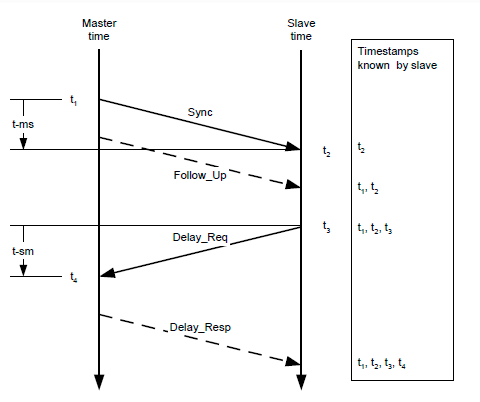
master and slave Clock pass Sync、Follow_Up、Delay_Req、Delay_Resp The interaction of these packets , obtain t1、t2、t3、t4 Time , The transmission path delay and the offset of the two clocks are calculated as follows :
Transmission path delay :
Time migration :
GPS The principle of time synchronization
GPS Clock source PPS The port sends hardware pulses every second (PPS The signal ), Then the data port sends a time information corresponding to the rising edge of the pulse (GPRMC Format ).
Livox The device received PPS The rising edge of the signal , And by the GPRMC After the data is parsed into the correct time information , The point cloud time will be set to GPS Time , And keep this time benchmark continuously accumulating , To achieve and GPS Time synchronization of the device .
Be careful :
Livox Hub Can receive directly RS485 Level GPRMC The signal ;
Livox LiDAR Cannot receive directly GPRMC The signal , Need to put GPRMC Data port access PC, And then through sdk The protocol is sent to radar
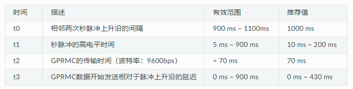
PPS Signals and GPRMC Signal timing requirements :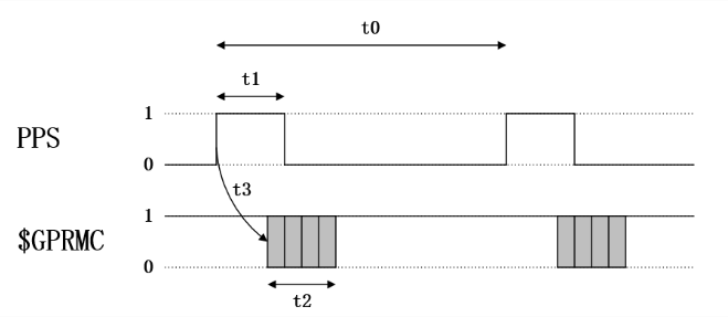
PPS The principle of time synchronization
Livox LiDAR Every time I receive PPS After the rising edge of the signal , The point cloud time at the current time will be set to 0, Then start counting again until the next PPS The pulse is coming . We can use this feature , To achieve PPS Pulse pair LiDAR Synchronization of time .
GPS+PPS How to use time synchronization
In order to be compatible with other manufacturers LiDAR Hardware ,Livox The device also supports GPS Time synchronization .
because Livox There are different kinds of hardware (LiDAR/Hub), In the use of GPS When the synchronization , Hardware interfaces can be divided into 3 class :
- Use Livox Hub;
- Use Livox Converter 1.0 Connected LiDAR( Such as :Mid-40、Mid-100);
- Use Livox Converter 2.0 Connected LiDAR( Such as :Tele-15、Horizon、Avia);
The following will introduce how to use this 3 Interface GPS Time synchronization .
Livox Hub
If GPS The time signal of the module and PPS The signal is RS485 level , Connect the line directly Hub Of GPS Time synchronization port (GPS sync port) that will do .
If GPS The time signal of the module and PPS The signal is TTL level , The following level conversion is required , To connect the signal Hub Of GPS Time synchronization port (GPS sync port).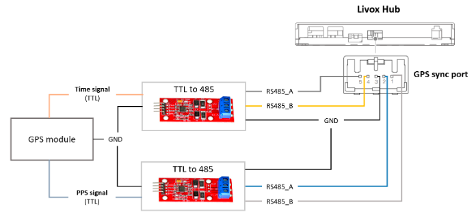
Hub Use GPS When the synchronization , There is no need for SDK Software configuration .
Livox Converter 1.0
take GPS The time signal of the module (GPRMC) adopt TTL turn usb Module access PC,PPS( Must be RS485 level ) Signal access LiDAR Synchronous port of adapter box (Sync Port).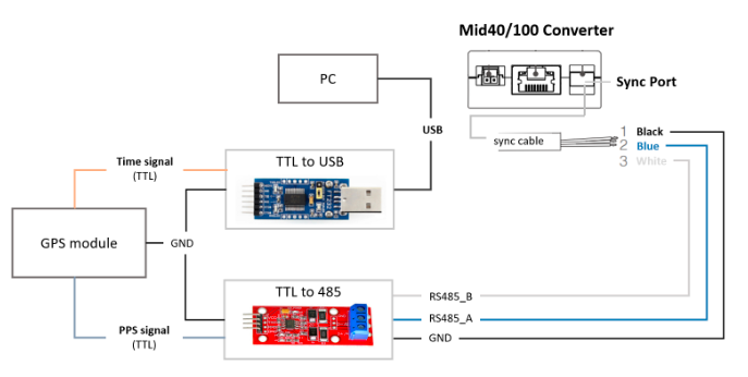
View access PC Of usb Port name of the module ,
for example /dev/ttyUSB0,
Add to livox_lidar_config.json In file “timesync_config” Of “device_name”,
And then “enable_timesync” Configure to true,
Baud rate “baudrate_index” You can refer to Livox_ros_driver To configure specific values
"timesync_config": {

    "enable_timesync": true,
    "device_name": "/dev/ttyUSB0",
    "comm_device_type": 0,
    "baudrate_index": 2,
    "parity_index": 0
    }
then function launch file
Livox Converter 2.0
take GPS The time signal of the module (GPRMC) adopt TTL turn usb Module access PC,PPS( Notice that this is TTL level ) Signal access LiDAR Synchronous port of adapter box (Sync Port).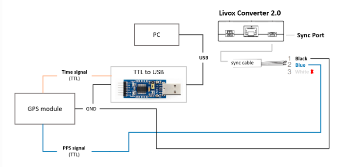
View access PC Of usb Port name of the module ,
for example /dev/ttyUSB0,
Add to livox_lidar_config.json In file “timesync_config” Of “device_name”,
And then “enable_timesync” Configure to true,
Baud rate “baudrate_index” You can refer to Livox_ros_driver To configure specific values
"timesync_config": {

    "enable_timesync": true,
    "device_name": "/dev/ttyUSB0",
    "comm_device_type": 0,
    "baudrate_index": 2,
    "parity_index": 0
    }
then function launch file
Status check
By viewing timestamp_type data ,
If timestamp_type by 3, It means that the equipment is in progress GPS Time synchronization :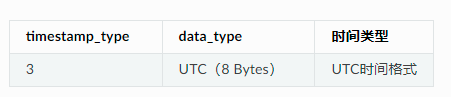
UTC Time format :
PPS How to use time synchronization
Livox LiDAR Every time I receive PPS After the rising edge of the signal , The point cloud time at the current time will be set to 0, Then start counting again until the next PPS The pulse is coming . We can use this feature , To achieve PPS Pulse pair LiDAR Synchronization of time .
The following is the pseudocode to implement this process :
// PPS Time Synchronization
static uint64_t lidar_time_last;
static uint64_t lidar_time_real;

// 1. Read the PPS rising edge time, Unit is nanosecond.
uint64_t pps_time_ns = get_pps_rising_nsecond();
// 2. Read LiDAR point time, Unit is nanosecond.
uint64_t lidar_time = get_lidar_pack_time();
// 3. Update real time.
if (lidar_time < lidar_time_last)
{

    //LiDAR time jump indicates the generation of PPS rising edge.
    lidar_time_real = pps_time_ns + lidar_time%(1000000000);
}
else
{

    lidar_time_real += lidar_time - lidar_time_last;
}
//Update history
lidar_time_last = lidar_time;
Obtain by other means PPS Time information of rising edge , Corresponds to... In the above code get_pps_rising_nsecond() Interface .
边栏推荐
- 【论文阅读|深读】ANRL: Attributed Network Representation Learning via Deep Neural Networks
- SchedulX V1.4.0及SaaS版发布,免费体验降本增效高级功能!
- Errors made in the development of merging the quantity of data in the set according to attributes
- Schedulx v1.4.0 and SaaS versions are released, and you can experience the advanced functions of cost reduction and efficiency increase for free!
- Input and output of C language pointer to two-dimensional array
- How can reinforcement learning be used in medical imaging? A review of Emory University's latest "reinforcement learning medical image analysis", which expounds the latest RL medical image analysis co
- Domestic images of various languages, software and systems. It is enough to collect this warehouse: Thanks mirror
- Make DIY welding smoke extractor with lighting
- 最近小程序开发记录
- centos8 用yum 安装MySQL 8.0.x
猜你喜欢
PartyDAO如何在1年内把一篇推文变成了2亿美金的产品DAO
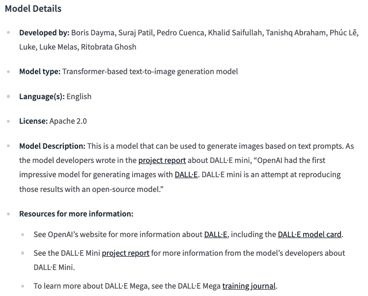
The mega version model of dall-e MINI has been released and is open for download

一片葉子兩三萬?植物消費爆火背後的“陽謀”
FLIR blackfly s industrial camera: configure multiple cameras for synchronous shooting

Big guys gather | nextarch foundation cloud development meetup is coming!
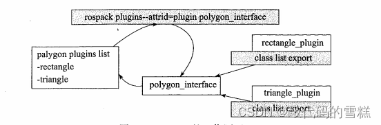
ROS学习(24)plugin插件
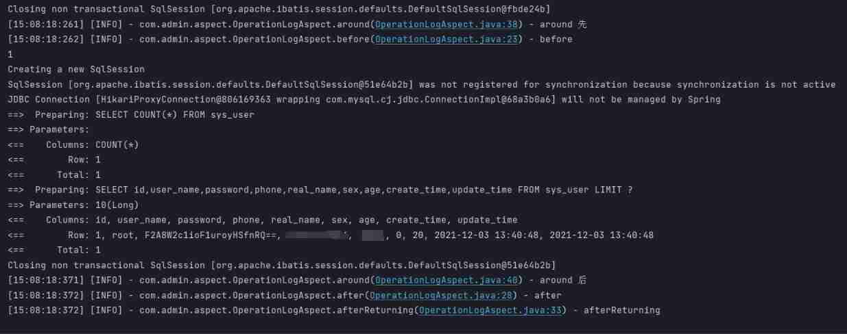
@Before, @after, @around, @afterreturning execution sequence
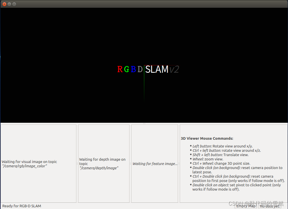
ROS学习(二十)机器人SLAM功能包——rgbdslam的安装与测试
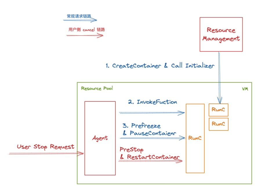
Decryption function calculates "task state and lifecycle management" of asynchronous task capability
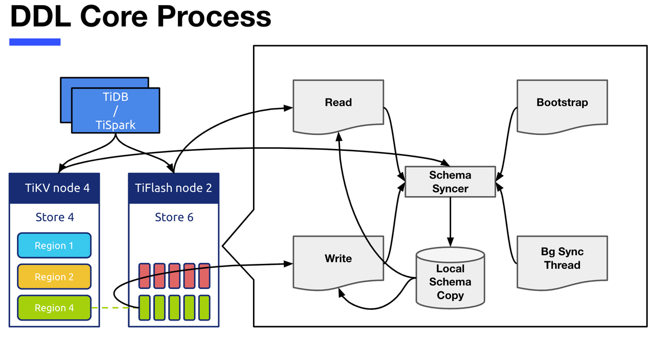
TiFlash 源码阅读(四)TiFlash DDL 模块设计及实现分析
随机推荐
How can I code for 8 hours without getting tired.
Flir Blackfly S 工业相机:配置多个摄像头进行同步拍摄
Date processing tool class dateutils (tool class 1)
FLIR blackfly s industrial camera: configure multiple cameras for synchronous shooting
MySQL's most basic select statement
最近小程序开发记录
机器人队伍学习方法,实现8.8倍的人力回报
ROS learning (24) plugin
【LeetCode】Day97-移除链表元素
Several classes and functions that must be clarified when using Ceres to slam
组合导航:中海达iNAV2产品描述及接口描述
2022 system integration project management engineer examination knowledge point: Mobile Internet
刨析《C语言》【进阶】付费知识【二】
[unique] what is the [chain storage structure]?
Word wrap when flex exceeds width
centos8 用yum 安装MySQL 8.0.x
一片葉子兩三萬?植物消費爆火背後的“陽謀”
SchedulX V1.4.0及SaaS版发布,免费体验降本增效高级功能!
Chang'an chain learning notes - certificate model of certificate research
BigDecimal 的正确使用方式