当前位置:网站首页>Simple network configuration for equipment management
Simple network configuration for equipment management
2022-07-07 12:08:00 【Chenjijjn】
Simple equipment management network scheme configuration
List of articles
Preface
Simple configuration scheme , There are some differences in the actual network , No protected backup is configured in the experiment .
One 、 Tube configuration steps
1, Use of in ring equipment OSPF Conduct network management signal communication
2, Use of ring head equipment and single hanging equipment EPL Dedicated line increase VLAN Transfer to the summary device
3, Summarize equipment usage EVPL Pass through all sites VLAN
4, Use at the special line IS-IS do IGP And enable the MPLS
5, Use 2 This is a special line ,MPLS L2 And L3 A dedicated line
Two 、 The topology
1. Here's the picture
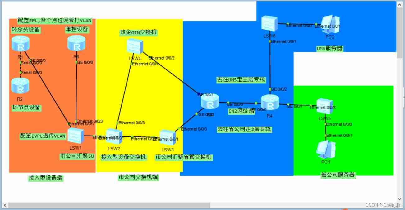
2. Introduction to equipment configuration
2.1 Communication configuration between ring node and ring head equipment
Use in the equipment room Serial simulation GCC signal communication
First configuration R2 The ring return port of IP Address ( For the node IP)
interface LoopBack0
 ip address 10.49.202.126 255.255.255.255
stay Serial Configure the borrowing ring return port address under the interface
interface Serial0/0/0
 link-protocol ppp
 ip address unnumbered interface LoopBack0
Then announce the loopback to OSPF in
ospf 1
 area 0.0.0.0
  network 10.49.202.126 0.0.0.0
R1 Of Serial The interface is also configured
interface LoopBack0
 ip address 10.49.202.62 255.255.255.255

 interface Serial0/0/0
 link-protocol ppp
 ip address unnumbered interface LoopBack0
Finally, we need to R1 The default route of is announced to R2 To guide the data forwarding of ring node devices
ospf 1
 default-route-advertise
 area 0.0.0.0
  network 10.49.202.62 0.0.0.0
At this point, we can make R2ping through R1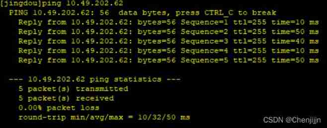
2.2 Simulate the configuration of ring head and single coupling node
R1 To configure
Use sub interface emulation EPL increase VLAN
interface GigabitEthernet0/0/0.2021
 dot1q termination vid 2021
 ip address 10.49.255.185 255.255.255.252
 arp broadcast enable
Configure a default route to the convergence switch
ip route-static 0.0.0.0 0.0.0.0 10.49.255.186
R6 Also configure sub interfaces and nodes IP And default routing
interface GigabitEthernet0/0/0.2031
 dot1q termination vid 2031
 ip address 10.49.255.177 255.255.255.252
 arp broadcast enable
interface LoopBack0
 ip address 10.49.203.62 255.255.255.255
ip route-static 0.0.0.0 0.0.0.0 10.49.255.178
2.3 Use LSW1 Switches simulate convergence devices EVPL function
To configure VLAN And bind the interface through 0/0/2 The interface transmits data to the convergence switch
interface Ethernet0/0/1
 port link-type trunk
 port trunk allow-pass vlan 2021
# interface Ethernet0/0/2
 port link-type trunk
 port trunk allow-pass vlan 2021 2031
# interface Ethernet0/0/3
 port link-type trunk
 port trunk allow-pass vlan 2031
2.4 Municipal Company convergence switch configuration
First configure the corresponding device VLANIF Address
interface Vlanif2021
 description anxi
 ip address 10.49.255.186 255.255.255.252
# interface Vlanif2031
 description tongmei
 ip address 10.49.255.178 255.255.255.252
To configure VLAN release
interface Ethernet0/0/1
 port link-type trunk
 port trunk allow-pass vlan 2021 2031
Continue configuration 2 individual VLANIF The addresses lead to 2 A direction
interface Vlanif301
 description to shenggongsi
 ip address 10.49.128.1 255.255.255.252
# interface Vlanif501
 description to ums
 ip address 10.49.254.1 255.255.255.252
interface Ethernet0/0/2
 port link-type trunk
 port trunk allow-pass vlan 301
# interface Ethernet0/0/3
 port link-type trunk
 port trunk allow-pass vlan 501
Configure the static routing table of each service direction
ip route-static 10.49.202.0 255.255.255.0 10.49.255.185
ip route-static 10.49.203.0 255.255.255.0 10.49.255.177
ip route-static 10.255.255.0 255.255.255.0 10.49.254.2  UMS The server IP
ip route-static 172.31.255.41 255.255.255.255 10.49.128.2    Provincial company server IP
2.5 Let's first introduce CN2 The Internet L2 Dedicated line configuration ( Go to the provincial company to choose this special line )
To configure IS-IS And enable
R3:
isis 100
 network-entity 49.0001.0001.0000.00

 interface GigabitEthernet0/0/0
 ip address 10.0.0.1 255.255.255.252
 isis enable 100

interface LoopBack0
 ip address 3.3.3.3 255.255.255.255
 isis enable 100
R4:
isis 100
 network-entity 49.0001.0002.0000.00

interface GigabitEthernet0/0/0
 ip address 10.0.0.2 255.255.255.252
 isis enable 100

interface LoopBack0
 ip address 4.4.4.4 255.255.255.255
 isis enable 100
Then the interface is enabled MPLS And enable the L2VPN And LDP
R3:
mpls lsr-id 3.3.3.3
mpls
# mpls l2vpn
# mpls ldp
R4:
mpls lsr-id 4.4.4.4
mpls
# mpls l2vpn
# mpls ldp
stay R3 And R4 Configure
mpls
mpls ldp
R3 Configure remote neighbors on
mpls ldp remote-peer 4.4.4.4
R4 Configure remote neighbors on
mpls ldp remote-peer 3.3.3.3
choose R3 Of G0/0/2 The port is connected to the convergence server of the municipal company , stay G0/0/2 Port configuration dedicated line service
interface GigabitEthernet0/0/2
 mpls l2vc 4.4.4.4 100 control-word
 mpls l2vpn pw bfd
R4 choose G0/0/1 Connect to the servers of provincial companies and configure special line Services
interface GigabitEthernet0/0/1
 mpls l2vc 3.3.3.3 100 control-word
 mpls l2vpn pw bfd
thus R3 Of G0/0/2 And R4 Of G0/0/1 Between them is equivalent to a network cable
2.5.1 Network management switch of municipal company LSW3 Network management switch with provincial company LSW5 Inter configuration , Route selection BGP, Later, announce the static route to BGP.
LSW3 And LSW5 To configure VLANIF Address and bind to port
LSW3: Use E0/0/3 docking R3 G0/0/2
interface Vlanif201
 description bgp
 ip address 172.0.100.1 255.255.255.252
interface Ethernet0/0/3
 port link-type access
 port default vlan 201
LSW5: Use E0/0/2 docking R4G0/0/1
interface Vlanif201
 description bgp
 ip address 172.0.100.2 255.255.255.252
interface Ethernet0/0/2
 port link-type access
 port default vlan 201
LSW3 Enable BGP And announce the static route to the device
bgp 65533
 router-id 172.0.100.1
 peer 172.0.100.2 as-number 65533
 # ipv4-family unicast
  undo synchronization
  network 10.49.128.0 255.255.128.0
  peer 172.0.100.2 enable
# ip route-static 10.49.128.0 255.255.128.0 10.49.128.1
LSW5 Enable BGP And announce the direct route to the equipment
bgp 65533
 router-id 172.0.100.2
 peer 172.0.100.1 as-number 65533
 # ipv4-family unicast
  undo synchronization
  import-route direct
  peer 172.0.100.1 enable
At this point, the ring node device can PING Tongsheng company server 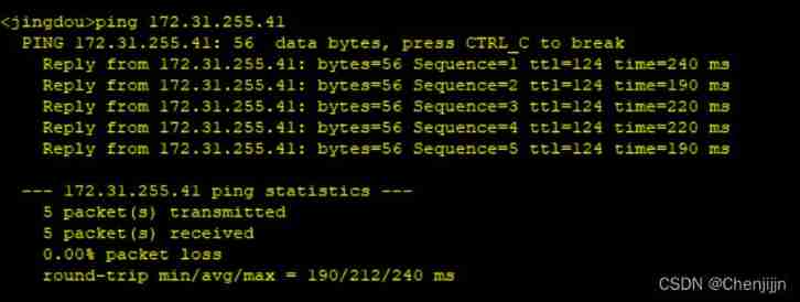 2.6 Go to UMS Of L3 Dedicated line configuration or use R3 And R4
R3 To configure : First configure a VPN INTSTANCE
ip vpn-instance UMS
 ipv4-family
  route-distinguisher 100:100
  vpn-target 200:200 export-extcommunity
  vpn-target 200:200 import-extcommunity
And then VPN Bind to sub interface
interface GigabitEthernet0/0/1.101
 dot1q termination vid 101
 ip binding vpn-instance UMS
 ip address 172.0.0.1 255.255.255.252
 arp broadcast enable
Enable BGP Of MPSL VPNV4 And introduce direct connection and static routing
bgp 65535
 router-id 3.3.3.3
 peer 4.4.4.4 as-number 65535
 peer 4.4.4.4 connect-interface LoopBack0
 # ipv4-family unicast
  undo synchronization
  peer 4.4.4.4 enable
  peer 4.4.4.4 next-hop-local
 # ipv4-family vpnv4
  policy vpn-target
  peer 4.4.4.4 enable
 # ipv4-family vpn-instance UMS
  import-route direct
  import-route static
# ip route-static vpn-instance UMS 10.49.128.0 255.255.128.0 172.0.0.2
R4 To configure : Also configure VPN INSTANCE
ip vpn-instance UMS
 ipv4-family
  route-distinguisher 100:101
  vpn-target 200:200 export-extcommunity
  vpn-target 200:200 import-extcommunity
take VPN Bind to sub interface
interface GigabitEthernet0/0/2.101
 dot1q termination vid 101
 ip binding vpn-instance UMS
 ip address 172.0.10.1 255.255.255.252
 arp broadcast enable
Also enable BGP MPLS VPNV4 And introduce the route into
bgp 65535
 router-id 4.4.4.4
 peer 3.3.3.3 as-number 65535
 peer 3.3.3.3 connect-interface LoopBack0
 # ipv4-family unicast
  undo synchronization
  peer 3.3.3.3 enable
  peer 3.3.3.3 next-hop-local
 # ipv4-family vpnv4
  policy vpn-target
  peer 3.3.3.3 enable
 # ipv4-family vpn-instance UMS
  import-route direct
  import-route static
# ip route-static vpn-instance UMS 10.255.255.0 255.255.255.0 172.0.10.2
thus L3 The special line has been opened
2.7 Go to UMS Of 2 Switches LSW4 LSW6 To configure
LSW4 To configure :
To configure 2 individual VLANIF The communication address is bound to the port to the dedicated line router and the municipal convergence switch
 interface Vlanif101
 ip address 172.0.0.2 255.255.255.252
# interface Vlanif501
 ip address 10.49.254.2 255.255.255.252
# interface Ethernet0/0/1
 port link-type trunk
 port trunk allow-pass vlan 501
# interface Ethernet0/0/2
 port link-type trunk
 port trunk allow-pass vlan 101
Configure the static routing table
ip route-static 10.49.128.0 255.255.128.0 10.49.254.1
ip route-static 10.255.255.0 255.255.255.0 172.0.0.1
LSW6 To configure :
It's also configuration 2 individual VLANIF The communication address is from the server to the dedicated line router
interface Vlanif101
 ip address 172.0.10.2 255.255.255.252
# interface Vlanif501
 ip address 10.255.255.1 255.255.255.0
# interface Ethernet0/0/1
 port link-type trunk
 port trunk allow-pass vlan 101
# interface Ethernet0/0/2
 port link-type access
 port default vlan 501
Configure another static route
ip route-static 10.49.128.0 255.255.128.0 172.0.10.1
At this point, the ring node equipment can also PING through ums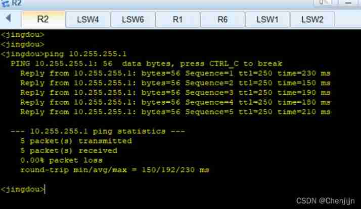
边栏推荐
- 【滤波跟踪】基于matlab扩展卡尔曼滤波EKF和无迹卡尔曼滤波UKF比较【含Matlab源码 1933期】
- 《通信软件开发与应用》课程结业报告
- SwiftUI 教程之如何在 2 秒内实现自动滚动功能
- Swiftui tutorial how to realize automatic scrolling function in 2 seconds
- [filter tracking] strapdown inertial navigation simulation based on MATLAB [including Matlab source code 1935]
- 【滤波跟踪】基于matlab捷联惯导仿真【含Matlab源码 1935期】
- 软件内部的定时炸弹:0-Day Log4Shell只是冰山一角
- 18 basic introduction to divider separator component of fleet tutorial (tutorial includes source code)
- 110.网络安全渗透测试—[权限提升篇8]—[Windows SqlServer xp_cmdshell存储过程提权]
- About how to install mysql8.0 on the cloud server (Tencent cloud here) and enable local remote connection
猜你喜欢

HCIA复习整理

Unity 贴图自动匹配材质工具 贴图自动添加到材质球工具 材质球匹配贴图工具 Substance Painter制作的贴图自动匹配材质球工具

【数据聚类】基于多元宇宙优化DBSCAN实现数据聚类分析附matlab代码

Introduction and application of smoothstep in unity: optimization of dissolution effect
Completion report of communication software development and Application

Unity map auto match material tool map auto add to shader tool shader match map tool map made by substance painter auto match shader tool
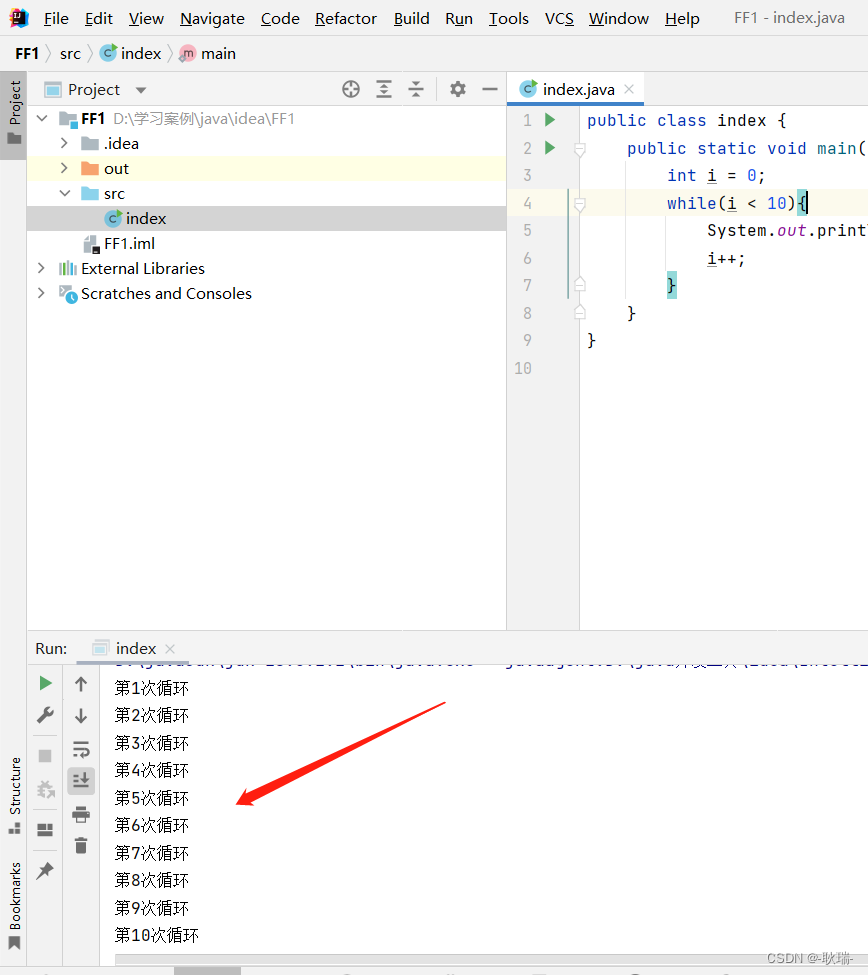
idea 2021中文乱码
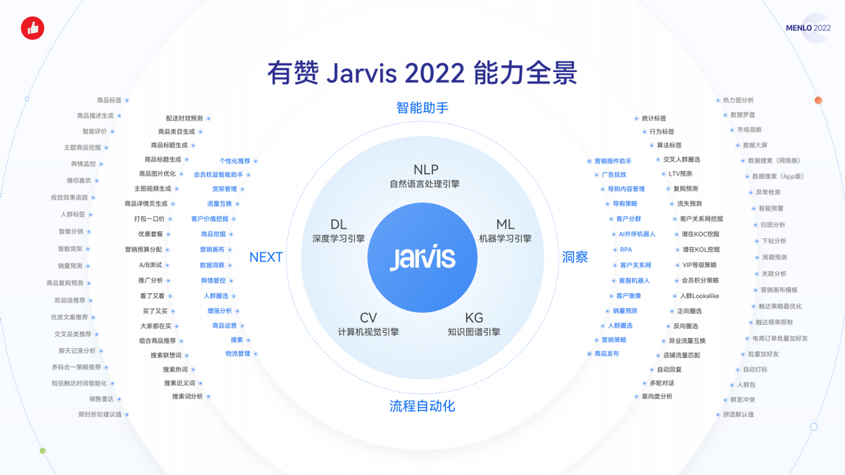
Upgrade from a tool to a solution, and the new site with praise points to new value
![110. Network security penetration test - [privilege promotion 8] - [windows sqlserver xp_cmdshell stored procedure authorization]](/img/62/1ec8885aaa2d4dca0e764b73a1e2df.png)
110. Network security penetration test - [privilege promotion 8] - [windows sqlserver xp_cmdshell stored procedure authorization]

Cmu15445 (fall 2019) project 2 - hash table details
随机推荐
Fleet tutorial 19 introduction to verticaldivider separator component Foundation (tutorial includes source code)
盘点JS判断空对象的几大方法
Various uses of vim are very practical. I learned and summarized them in my work
110. Network security penetration test - [privilege promotion 8] - [windows sqlserver xp_cmdshell stored procedure authorization]
Swiftui swift internal skill how to perform automatic trigonometric function calculation in swift
【玩转 RT-Thread】 RT-Thread Studio —— 按键控制电机正反转、蜂鸣器
数据库系统原理与应用教程(010)—— 概念模型与数据模型练习题
Present pod information to the container through environment variables
如何理解服装产业链及供应链
顶级域名有哪些?是如何分类的?
千人规模互联网公司研发效能成功之路
How to connect 5V serial port to 3.3V MCU serial port?
Internet Protocol
总结了200道经典的机器学习面试题(附参考答案)
Unity中SmoothStep介绍和应用: 溶解特效优化
Complete collection of common error handling in MySQL installation
MySQL安装常见报错处理大全
[data clustering] realize data clustering analysis based on multiverse optimization DBSCAN with matlab code
VIM command mode and input mode switching
Swiftui tutorial how to realize automatic scrolling function in 2 seconds