当前位置:网站首页>16. [stm32] starting from the principle, I will show you the DS18B20 temperature sensor - four digit digital tube displays the temperature
16. [stm32] starting from the principle, I will show you the DS18B20 temperature sensor - four digit digital tube displays the temperature
2022-07-05 15:48:00 【According to point_ DW】
Author's brief introduction : Hello, everyone , My name is DW, Share some of my new knowledge every day , Look forward to making progress with you
Series column :STM32
Small experimental target : Display on the four digit nixie tube DS18B20 Collected temperature value
If there is anything that is not well written, you are welcome to correctDevelopment board : The punctual atoms STM32F103Mini edition
Creation time :2022 year 6 month 1 JapanRecently, I took the driver's license and was busy with my graduation thesis , Stop changing 20 Many days , Resume the update from today , Next, continue to update some commonly used sensors , Look forward to making progress with you !!
Catalog
1. Digital temperature sensor (DS18B20)
2. Writing of operation function
-------------------------------
-------------------------------
1. Digital temperature sensor (DS18B20)
DS18B20 have It has a unique first-line interface , Only one port line is needed to communicate with multiple points , It simplifies the application of distributed temperature sensing without external components and can be powered by data bus , The voltage range is 3.0 V to 5.5 V No backup power supply is required The measuring temperature range is -55 ° C to +125 ℃ .
DS18B20 It can be programmed 9~12 Bit resolution , The temperature is converted to 12 The maximum value of the bit number format is 750 millisecond , Accuracy of :±0.5°C. Smaller packaging options , Wider voltage application range . Resolution setting , And the alarm temperature set by the user is stored in EEPROM in , Save after power failure .
DS18B20 Its performance is the best in the new generation of products ! The performance price ratio is also excellent ! because DS18B20 It is an interface line communication , So the central microprocessor and DS18B20 Only one port line is connected . Energy can be obtained from the data line itself for reading, writing and temperature conversion , No external power supply is required . Because every one of them DS18B20 Contains a unique serial number , Multiple DS18B20 Can exist on one bus at the same time . It has many uses , Including air conditioning environment control , A device or machine that senses the temperature inside a building , And process monitoring and control .
DS18B20 Physical drawing and pin package drawing
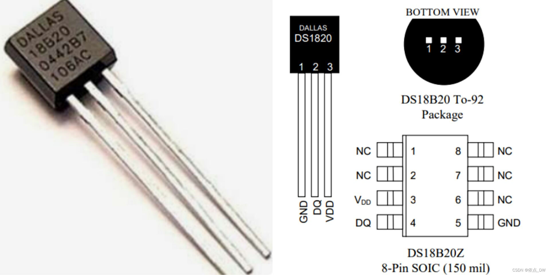
Facing the flat side , Left minus right positive , Once the connection is reversed, it will immediately get hot , It may burn down ! meanwhile , The reverse connection also causes the sensor to always display 85℃ Why . In actual operation, the positive and negative are inversely connected , The sensor heats up immediately , The LCD screen cannot display the reading , After the positive and negative are connected, it shows 85℃.
DS18B20 Pin description :
- GND: Power ground wire
- DQ: Digital signal input / Output terminal .
- VDD: External power supply input terminal .
DS18B20 And STM32 Connection wiring diagram :
- GND: The earth
- DQ: Pick up PA0 At the same time, connect a pull-up resistor
- VDD:3.3V

External pull-up resistance :
DS18B20 The operating current is about 1mA,VCC It's usually 5V, Then the resistance R=5V/1mA=5KΩ, Therefore, a similar resistance is connected 5.1kΩ resistance .
2. Writing of operation function
1.DS18B20 Function initialization
void DS18B20_UserConfig(void){

	GPIO_InitTypeDef GPIO_InitStructure;// Defining structure

	RCC_APB2PeriphClockCmd(RCC_APB2Periph_GPIOA,ENABLE);// To configure PB0 The clock

	GPIO_InitStructure.GPIO_Pin = DS18B20;//PA0
	GPIO_InitStructure.GPIO_Speed = GPIO_Speed_10MHz;// Port output rate
	GPIO_InitStructure.GPIO_Mode = GPIO_Mode_Out_PP;// Push pull output mode
	GPIO_Init(DS18B20_PROT,&GPIO_InitStructure);// Initial serial port
}
2. Switch DS18B20 Output input pin function
// Input / output mode selection function
void Output_Input_Mode(u8 cmd){

	GPIO_InitTypeDef GPIO_InitStructure;// Defining structure

	if(cmd){//1: The output mode

	GPIO_InitStructure.GPIO_Pin = DS18B20;//PB0
	GPIO_InitStructure.GPIO_Speed = GPIO_Speed_10MHz;// Port output rate
	GPIO_InitStructure.GPIO_Mode = GPIO_Mode_Out_PP;// Push pull output mode
	}
	else{//0: The input mode

	GPIO_InitStructure.GPIO_Pin = DS18B20;//PB0
	GPIO_InitStructure.GPIO_Mode = GPIO_Mode_IPU;// Pull up mode
	}
	GPIO_Init(DS18B20_PROT,&GPIO_InitStructure);// Initial serial port
}
3. DS18B20 Start sequence

As can be seen from the above figure ,VCC For power , The middle line is the data line ,GND For the land . First step , Use the MCU to send instructions to output the data line pin to low level and keep 480us Time for , after , Release the bus ( pull up , Time delay 30us); second , after DS18B20 Start to feedback the signal to the MCU , Feedback whether its pulse exists or not , If DS18B20 There is , It will be 60-240us It feeds back a low level to the MCU , We can know by reading this level signal DS18B20 Whether there is , The specific functions are as follows :
// Start signal   Judge success
u8 DS18B20_Start_Signal(void){

	u8 data;

	// Write
	Output_Input_Mode(1);// The input mode
	DS18B20_Low;
	delay_us(480);
	DS18B20_High;
	delay_us(30);

	// Read pin status  1:DS18B20 Failure  0:DS18B20 success
	Output_Input_Mode(0);// The output mode
	data = GPIO_ReadInputDataBit(DS18B20_PROT,DS18B20);// Read input status   60~240us
	delay_us(200);//200us  480+30+240=750  960-750=210   take 200us that will do

	return data;
}
When we plug in DS18B20 after , The nixie tube shows 0, Pull out DS18B20 after , The nixie tube shows 1, That's what we have There is no problem starting the program .

4.DS18B20 Write timing

This sequence diagram consists of two parts , Write... Respectively “0” And write “1” operation , We just need to read and write “1” Just operate , Because if it's not “1” when , So that is “0”, At this time, the system will automatically fill “0”.
We need to write data one by one , A byte needs to be written eight times . When writing data, you need to configure the data pin as push-pull output , Written by “1” Part of the sequence diagram can be seen , We need to lower the bus time >1us, We choose to delay 2us that will do ,2us Then you can write data to the bus , You can write data to the bus ;DS18B20 First out of the low and then out of the high , So we need to move the data from high to low , But you need to judge the low order first every time ; After writing , We need a certain delay , The delay time is :15us+30us=40us, This time is the time when the data is written to the corresponding register , Finally, pull up the bus and release the bus , Then move the data to the right by one bit each time , In this way, the second frame data can be written .
// towards DS18B20 Writing data
// Write : The output mode  1
void DS18B20_Write_Byte(u8 data){


	for(u8 i=0;i<8;i++){

		Output_Input_Mode(1);
		DS18B20_Low;
		delay_us(2);

		((data&0x01)) ? DS18B20_High : DS18B20_Low;//DS18B20  Low first out , so &0x01
		delay_us(45);
		DS18B20_High;// Pull up the bus

		data>>=1;// Shift the data right eight times   Finish writing 8bit data
	}
}
5. DS18B20 Reading sequence

The reading sequence needs to have a return value , So define a function with a return value . Before reading data from the bus, the data needs to be shifted , Then configure the data cable IO The state of the mouth , Write the pin , Pull down the data pin , Time delay 2us Then pull up the data pin ; Then read ,IO Port selection is input mode , If the data read is “1”, Just or up “1”, Otherwise, the system will automatically fill “0”, Because the time of reading operation process is the same as that of writing operation process , Therefore, it also needs to increase 45us Time delay of .
// read DS18B20 data
// read : The input mode  0
u8 DS18B20_Read_Byte(void){

	u8 data;

	for(u8 i=0;i<8;i++){

		data>>=1;
		Output_Input_Mode(1);
		DS18B20_Low;
		delay_us(2);
		DS18B20_High;// Pull up the bus

		Output_Input_Mode(0);
		if(GPIO_ReadInputDataBit(DS18B20_PROT,DS18B20) == SET){

			data |= 0x80;// From the top
		}
			delay_us(45);
	}
	return data;
}
6. Temperature conversion
Temperature register format and temperature / Data correspondence 
Ds18b20 use 12 The highest bit of bit storage temperature value is symbol bit, and the figure below is 18b20 Temperature storage mode , Negative temperature S = 1/ Positive temperature S = 0 .
The transmission mode is to transmit the low bit first and then the high bit .
The configuration register allows the user to set 9 position ,10 position ,11 Bit and 12 Bit temperature resolution , The resolution corresponding to temperature is :0.5°C,0.25°C,0.125°C,0.0625°C
The default is 12 Bit resolution :0.0625°C
(1) Send start signal , Write instructions to the bus ;
(2) Because the low order is read first (LSB). Read high (MSB), Therefore, it is necessary to consolidate data (temp);
(3) Temperature conversion formula , Negative temperature conversion : Inverse code +1;
// Get the temperature value
void DS18B20_Read_Temperature(u16 *data){

	u8 LSB = 0,MSB = 0;
	u16 temp;
	// Temperature conversion
	DS18B20_Start_Signal();
	DS18B20_Write_Byte(0xcc);// skip ROM
	DS18B20_Write_Byte(0x44);// Temperature change
	//delay_ms(750);
	//12 Bit accuracy  750ms   The nixie tube itself has a time delay , So this delay can be removed

	// Read register
	DS18B20_Start_Signal();
	DS18B20_Write_Byte(0xcc);// skip ROM
	DS18B20_Write_Byte(0xbe);// Read temporary storage

	LSB =  DS18B20_Read_Byte();
	MSB =  DS18B20_Read_Byte();
	temp = (MSB<<8) | LSB;// Merge data into 16 position

	if((temp&0xf800) == 0xf800){ // Negative temperature ;s=1	 Positive temperature : s=0

		*data =(((~temp+0x01)*-0.0625)+0.5)*10.0;
	}
	else{

		*data =((temp*0.0625)+0.5)*10.0;
	}
}
After burning the program , You can see the corresponding temperature displayed by the four digit nixie tube .
Okay , Today's sharing is here , If you feel useful, remember to collect and praise , Thank you. !
This chapter ends , I'll see you in the next chapter
Reference material :
1.STM32 Firmware library manual
2. The punctual atoms STM32 Incomplete manual _ Library function version
3. Reference video
4. Fundamentals of digital electronic technology
5.15.[STM32] An article teaches you to use 75HC595 The chip drives the four digit nixie tube
Data uploaded , You need to take it yourself
边栏推荐
猜你喜欢
CSRF, XSS science popularization and defense
把 ”中台“ 的思想迁移到代码中去
Common redis data types and application scenarios
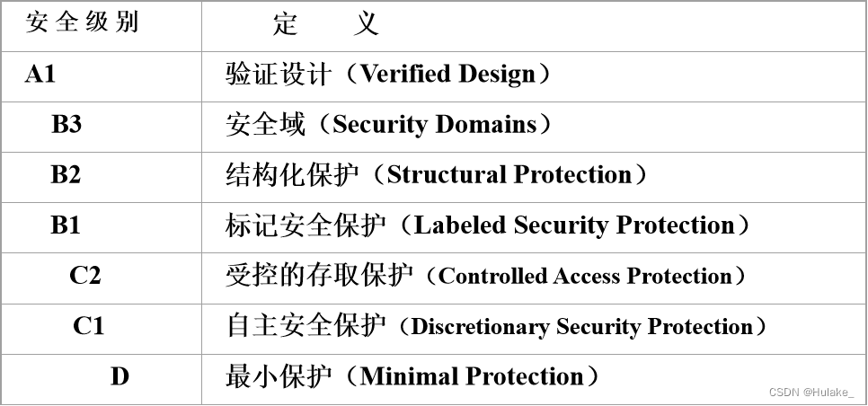
数据库学习——数据库安全性
Bugku cyberpunk
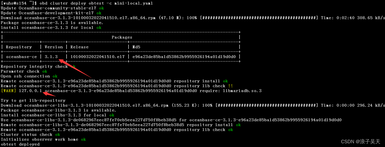
OceanBase社区版之OBD方式部署方式本地安装
基于OpenHarmony的智能金属探测器
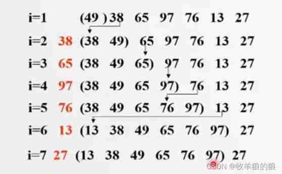
Bubble sort, insert sort
MySQL 巨坑:update 更新慎用影响行数做判断!!!
MySQL giant pit: update updates should be judged with caution by affecting the number of rows!!!
随机推荐
19.[STM32]HC_SR04超声波测距_定时器方式(OLED显示)
Redis distributed lock principle and its implementation with PHP (1)
Example of lvgl display picture
助力数字经济发展,夯实数字人才底座—数字人才大赛在昆成功举办
MySQL table field adjustment
Bugku easy_ nbt
Data communication foundation - route republication
CSDN I'm coming
MySQL5.7的JSON基本操作
Fundamentals of data communication - Principles of IP routing
数学建模之层次分析法(含MATLAB代码)
lv_ font_ Conv offline conversion
Transfer the idea of "Zhongtai" to the code
Detailed explanation of C language branch statements
Huiyuan, 30, is going to have a new owner
wyt 。。
The difference between SQL Server char nchar varchar and nvarchar
1330: [example 8.3] minimum steps
Optional parameters in the for loop
queryRunner. Query method