当前位置:网站首页>FLIR blackfly s industrial camera: synchronous shooting of multiple cameras through external trigger
FLIR blackfly s industrial camera: synchronous shooting of multiple cameras through external trigger
2022-07-07 02:01:00 【The moon shines on the silver sea like a dragon】
Flir Blackfly S Industrial camera : Realize synchronous shooting of multiple cameras through external trigger
Preface
In this blog Flir Blackfly S Industrial camera : Configure multiple cameras for synchronous shooting This paper introduces how to shoot synchronously with multiple cameras through the main and auxiliary cameras .
There is another way to achieve synchronous shooting of multiple cameras , That is, through external triggering , The trigger signals of all cameras are connected to the same touch source , You can strictly realize synchronous shooting
This blog mainly introduces How to use STM32F4 Of TIM14 To produce PWM Output , The output frequency is 20hz And 25hz, The proportion of high level is before the cycle 10%. Realize the generation of synchronous signal .
PWM brief introduction
PWM Definition :
Pulse width modulation (PWM), It's English “Pulse Width Modulation” Abbreviation , Short for pulse width modulation .
PWM It is a very effective technology to control analog circuit by using digital output of microprocessor .
A little bit more simple , It's the control of pulse width ,
PWM Principle diagram 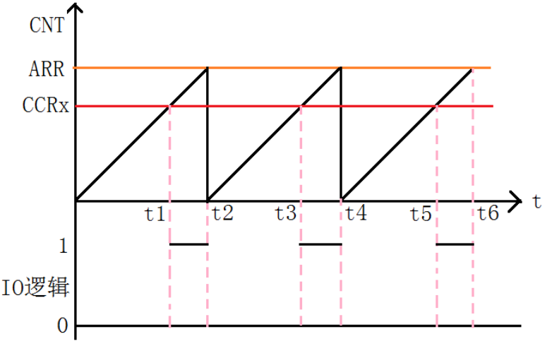
There's a PWM Schematic diagram . This picture must be well understood .
In the figure , Suppose the timer works in the up count PWM Pattern , And when CNT<CCRx when , Output 0, When CNT>=CCRx Time output 1.( Specifically, it is smaller than the output 0 still 1 You can set )
Then you can get the above PWM Sketch Map : When CNT Less than CCRx When ,IO Output low level (0), When CNT A value greater than or equal to CCRx When ,IO Output high level (1), When CNT achieve ARR When it's worth it , Back to zero , And then count up again , In turn, cycle .
change CCRx Value , You can change PWM The duty cycle of the output , change ARR Value , You can change PWM The frequency of the output , This is it. PWM The principle of output .
STM32F4 In addition to TIM6 and 7. Other timers can be used to generate PWM Output . One of the advanced timers TIM1 and TIM8 It can produce as many as 7 On the road PWM Output . And universal timers can also generate up to 4 On the road PWM Output . Here we only use TIM14 Of CH1 All the way to PWM Output .
PWM register
To make STM32F4 Universal timer TIMx produce PWM Output , use 3 A register , To control PWM Of .
These three registers are :
- Capture / Compare mode register (TIMx_CCMR1/2)
- Capture / Compare enable register (TIMx_CCER)
- Capture / Compare register (TIMx_CCR1~4)
Briefly introduce these three registers :
1: Capture / Compare mode register (TIMx_CCMR1/2), This register generally has 2 individual :TIMx _CCMR1 and TIMx _CCMR2. however TIM14 only one .TIMx_CCMR1 control CH1 and 2, and TIMx_CCMR2 control CH3 and 4.
Now we will use TIM14 For example
TIM14_CCMR1 The register bits are described in the figure Shown : Some bits of this register are in different modes , Function differently . Divide the registers 2 layer , The upper layer corresponds to output and the lower layer corresponds to input .
Mode setting bit OC1M, This part is made up of 3 A composition . A total of... Can be configured 7 Patterns ,
We use PWM Pattern , So this 3 Bit must be set to 110/111.110 and 111 These two kinds of PWM The difference between modes is that the polarity of the output level is opposite .
CC1S Used to set the direction of the channel ( Input / Output ) The default setting is 0, Is to set the channel as the output .
Be careful : This is because of our TIM14 Only 1 Channels , So only the eighth place is valid , The upper eight bits are invalid , Other timers with multiple channels , The top eight is also valid
2:TIM14 Capture of / Compare enable register (TIM14_CCER), This register controls the switch of each input and output channel . The description of each bit of this register is shown in Fig Shown :
This register is relatively simple , We only use CC1E position , This bit is an input / Capture 1 Output enable bit , If you want to PWM from IO output , This bit must be set to 1, So we need to set this bit to 1.
Again , because TIM14 Only 1 Channels , So only the lower four digits are valid , If it is another timer , Other bits of this register may also be valid .
3: Capture / Compare register (TIMx_CCR1~4), This register has 4 individual , Corresponding 4 Channels CH1~4. however TIM14 only one , namely :TIM14_CCR1, The description of each bit of the register is shown in the figure :
position 15:0 CCR1[15:0]: Capture / Compare 1 value
If the passage CC1 To configure For export :
CCR1 To load into the actual capture / Compare 1 Register value ( Preload value )
If it doesn't pass TIMx_CCMR In register OC1PE Bit enable preload function , The written value is transferred directly to the current register . Otherwise, it will only take effect when an update event occurs ( Copy to the capture that actually works / Compare register 1) Actual capture / The comparison register contains the counter to be compared with TIMx_CNT Compare and compare in OC1 The value signaled on the output .
In output mode , The value of this register is the same as CNT Value comparison of , Generate corresponding actions according to the comparison results . Take advantage of this , By modifying the value of this register , You can control PWM The output pulse width of .
If it's a general timer , Then it is enough to configure the above three registers , But if it's an advanced timer , It also needs to be equipped with
Set up : Brake and deadband register (TIMx_BDTR), The description of each bit of the register is shown in the figure :
This register , We only need to pay attention to the highest position :MOE position , If you want an advanced timer PWM Normal output , Must be set MOE Position as 1, Otherwise there will be no output .
PWM Implementation method
Through TIM14_CH1 Output PWM, The following describes the steps to configure this function through library functions .
1 Turn on TIM14 and GPIO The clock , To configure PF9 Choose the reuse function AF9(TIM14) Output .
To use TIM14, We have to turn on TIM14 The clock of , To configure PF9 For reuse (AF9) Output , To achieve TIM14_CH1 Of PWM after PF9
Output . Library functions enable TIM14 The way to clock is :
RCC_APB1PeriphClockCmd(RCC_APB1Periph_TIM14,ENABLE); //TIM14 Clock enable
Also enable GPIOF The clock of
To configure PF9 Pin mapping to AF9, Reuse as timer 14, The function called is :
GPIO_PinAFConfig(GPIOF,GPIO_PinSource9,GPIO_AF_TIM14); //GPIOF9 Reuse as timer 14
The last set PF9 Output for reuse function , Only... Are listed here GPIO A line of code initialized to the reuse function :
GPIO_InitStructure.GPIO_Mode = GPIO_Mode_AF; // Reuse function
For the pin relationship of timer channel , You can see STM32F4 The corresponding data book , such as PWM , We use timers 14 The passage of 1, Corresponding pin PF9 You can see from the data book table :
2 initialization TIM14, Set up TIM14 Of ARR and PSC Equal parameter .
In the open TIM14 After the clock , We need to set ARR and PSC Two registers to control the output PWM The cycle of .
The library function is through TIM_TimeBaseInit Functionally implemented , The format of the call is :
TIM_TimeBaseStructure.TIM_Period = arr; // Set auto reload load value
TIM_TimeBaseStructure.TIM_Prescaler =psc; // Set the prescaler value
TIM_TimeBaseStructure.TIM_ClockDivision = 0; // Set the clock split :TDTS = Tck_tim
TIM_TimeBaseStructure.TIM_CounterMode = TIM_CounterMode_Up; // Upcount mode
TIM_TimeBaseInit(TIM3, &TIM_TimeBaseStructure); // Initialize... According to the specified parameters  TIMx  Of
3 Set up TIM14_CH1 Of PWM Pattern , Can make TIM14 Of CH1 Output .
Set up TIM14_CH1 by PWM Pattern ( The default is frozen )
In library functions ,PWM passageway
Setting is through the function TIM_OC1Init()~TIM_OC4Init() To set up , Different channels have different settings , here
We use channels 1, So the function used is TIM_OC1Init().
void TIM_OC1Init(TIM_TypeDef* TIMx, TIM_OCInitTypeDef* TIM_OCInitStruct);
Look at the structure TIM_OCInitTypeDef The definition of :
typedef struct
{

 uint16_t TIM_OCMode;
 uint16_t TIM_OutputState;
 uint16_t TIM_OutputNState; */
 uint16_t TIM_Pulse;
 uint16_t TIM_OCPolarity;
 uint16_t TIM_OCNPolarity;
 uint16_t TIM_OCIdleState;
 uint16_t TIM_OCNIdleState;
} TIM_OCInitTypeDef
Here are some member variables related to requirements :
- Parameters TIM_OCMode The setting mode is PWM Or output comparison , Here we are PWM Pattern .
- Parameters TIM_OutputState Used to set the compare output enable , That is to enable PWM Output to port .
- Parameters TIM_OCPolarity Used to set whether the polarity is high or low .
- Other parameters TIM_OutputNState,TIM_OCNPolarity,TIM_OCIdleState and TIM_OCNIdleState It's only used by advanced timers .
TIM_OCInitTypeDef TIM_OCInitStructure;
TIM_OCInitStructure.TIM_OCMode = TIM_OCMode_PWM1; // Choice mode  PWM
TIM_OCInitStructure.TIM_OutputState = TIM_OutputState_Enable; // Compare output enable
TIM_OCInitStructure.TIM_OCPolarity = TIM_OCPolarity_Low; // Low output polarity
TIM_OC1Init(TIM14, &TIM_OCInitStructure); // according to T The specified parameter initializes the peripheral TIM1 4OC1
4 Can make TIM14
TIM_Cmd(TIM14, ENABLE); // Can make TIM14
5 modify TIM14_CCR1 To control the duty cycle
After the above settings ,PWM In fact, it has started to output , It's just that the duty cycle and frequency are fixed , And we modify it TIM14_CCR1 You can control CH1 The output duty cycle of .
In library functions , modify TIM14_CCR1 The function of the duty cycle is :
void TIM_SetCompare1(TIM_TypeDef* TIMx, uint16_t Compare2);
For other channels , There is a function name , The function format is TIM_SetComparex(x=1,2,3,4)
Through the above 5 A step , We can control TIM14 Of CH1 Output PWM Wave .
Although the advanced timer is similar to the general timer , But if the advanced timer wants to output PWM, You must also set a
individual MOE position (TIMx_BDTR Of the 15 position ), To enable the main output , Otherwise it won't output PWM. Functions set by library functions
by :
void TIM_CtrlPWMOutputs(TIM_TypeDef* TIMx, FunctionalState NewState)
PWM Frequency settings
adopt PWM You can know the principle of , When the frequency of the timer is fixed ,PWM The period of is only related to ARR of , The timer can also set a frequency division coefficient , So the calculation is as follows
TIM14 The clock is 84M
The frequency division coefficient is a, The overload value is b.
pwm The frequency is 84M/(ab)
pwm The period is (ab)/84M
At the beginning , The purpose is to produce 25hz And 20hz The signal of , Then the settings can be as follows :
25hz:
		PWM_PSC = 84;// Division coefficient .---- The counting frequency is 84M/PWM_PSC = 1M hz
		PWM_ARR = 40000;// Reload value ----PWM frequency  (84M/PWM_PSC)/PWM_ARR = 25 hz
20hz:
		PWM_PSC = 84;// Division coefficient .---- The counting frequency is 84M/PWM_PSC = 1M hz
		PWM_ARR = 50000;// Reload value ----PWM frequency  (84M/PWM_PSC)/PWM_ARR = 25 hz
Code
The key part of the code is given below .
// adopt PWM Generate camera shooting signal
#define CAMERA_TRIGGER_20HZ 0
#define CAMERA_TRIGGER_25HZ 1

u32 PWM_PSC ;//PWM  The prescaled coefficients
u32 PWM_ARR ;//PWM  Reload value
float PWM_a;//PWM  Duty cycle
uint32_t PWM_CCR;//PWM  It's worth
int main(void)
{


	NVIC_PriorityGroupConfig(NVIC_PriorityGroup_2);// Set system interrupt priority group 2
	delay_init(168);  // Initialization delay function

  if(CAMERA_TRIGGER_25HZ)
	{

		PWM_PSC = 84;// Division coefficient .---- The counting frequency is 84M/PWM_PSC = 1M hz
		PWM_ARR = 40000;// Reload value ----PWM frequency  (84M/PWM_PSC)/PWM_ARR = 25 hz
		PWM_a = 0.1;// Duty cycle
	}else if(CAMERA_TRIGGER_20HZ)
	{

		PWM_PSC = 84;// Division coefficient .---- The counting frequency is 84M/PWM_PSC = 1M hz
		PWM_ARR = 50000;// Reload value ----PWM frequency  (84M/PWM_PSC)/PWM_ARR = 25 hz
		PWM_a = 0.1;// Duty cycle
	}

	PWM_CCR = (uint32_t)PWM_ARR*PWM_a;
 	TIM14_PWM_Init(PWM_ARR,PWM_PSC);	// Set up PWM cycle
	TIM_SetCompare1(TIM14,PWM_CCR);	// Modify the comparison value , Change the duty cycle

   while(1)
	{

 		//delay_ms(1);
	}
}
//TIM14 PWM Partial initialization
//PWM Output initialization
//arr: Auto reload value
//psc: Clock presplitting frequency
void TIM14_PWM_Init(u32 arr,u32 psc)
{

	// This part needs to be modified manually IO Port setup

	GPIO_InitTypeDef GPIO_InitStructure;
	TIM_TimeBaseInitTypeDef  TIM_TimeBaseStructure;
	TIM_OCInitTypeDef  TIM_OCInitStructure;

	RCC_APB1PeriphClockCmd(RCC_APB1Periph_TIM14,ENABLE);  	//TIM14 Clock enable
	RCC_AHB1PeriphClockCmd(RCC_AHB1Periph_GPIOF, ENABLE); 	// Can make PORTF The clock

	GPIO_PinAFConfig(GPIOF,GPIO_PinSource9,GPIO_AF_TIM14); //GPIOF9 Reuse as timer 14

	GPIO_InitStructure.GPIO_Pin = GPIO_Pin_9;           //GPIOF9
	GPIO_InitStructure.GPIO_Mode = GPIO_Mode_AF;        // Reuse function
	GPIO_InitStructure.GPIO_Speed = GPIO_Speed_100MHz;	// Speed 100MHz
	GPIO_InitStructure.GPIO_OType = GPIO_OType_PP;      // Push pull multiplex output
	GPIO_InitStructure.GPIO_PuPd = GPIO_PuPd_UP;        // Pull up
	GPIO_Init(GPIOF,&GPIO_InitStructure);              // initialization PF9

	TIM_TimeBaseStructure.TIM_Prescaler=psc-1;  // Timer frequency division
	TIM_TimeBaseStructure.TIM_CounterMode=TIM_CounterMode_Up; // Upcount mode
	TIM_TimeBaseStructure.TIM_Period=arr-1;   // Automatic reload load value
	TIM_TimeBaseStructure.TIM_ClockDivision=TIM_CKD_DIV1;

	TIM_TimeBaseInit(TIM14,&TIM_TimeBaseStructure);// Initialize the timer 14

	// initialization TIM14 Channel1 PWM Pattern
	TIM_OCInitStructure.TIM_OCMode = TIM_OCMode_PWM1; // Select timer mode :TIM Pulse width modulation mode 2
 	TIM_OCInitStructure.TIM_OutputState = TIM_OutputState_Enable; // Compare output enable
	TIM_OCInitStructure.TIM_OCPolarity = TIM_OCPolarity_High; // Output polarity :TIM High output polarity
	TIM_OC1Init(TIM14, &TIM_OCInitStructure);  // according to T The specified parameter initializes the peripheral TIM1 4OC1

	TIM_OC1PreloadConfig(TIM14, TIM_OCPreload_Enable);  // Can make TIM14 stay CCR1 Pre loaded registers on

  TIM_ARRPreloadConfig(TIM14,ENABLE);//ARPE Can make

	TIM_Cmd(TIM14, ENABLE);  // Can make TIM14


}
Result
Check the two signals through the oscilloscope
25hz The signal is as follows :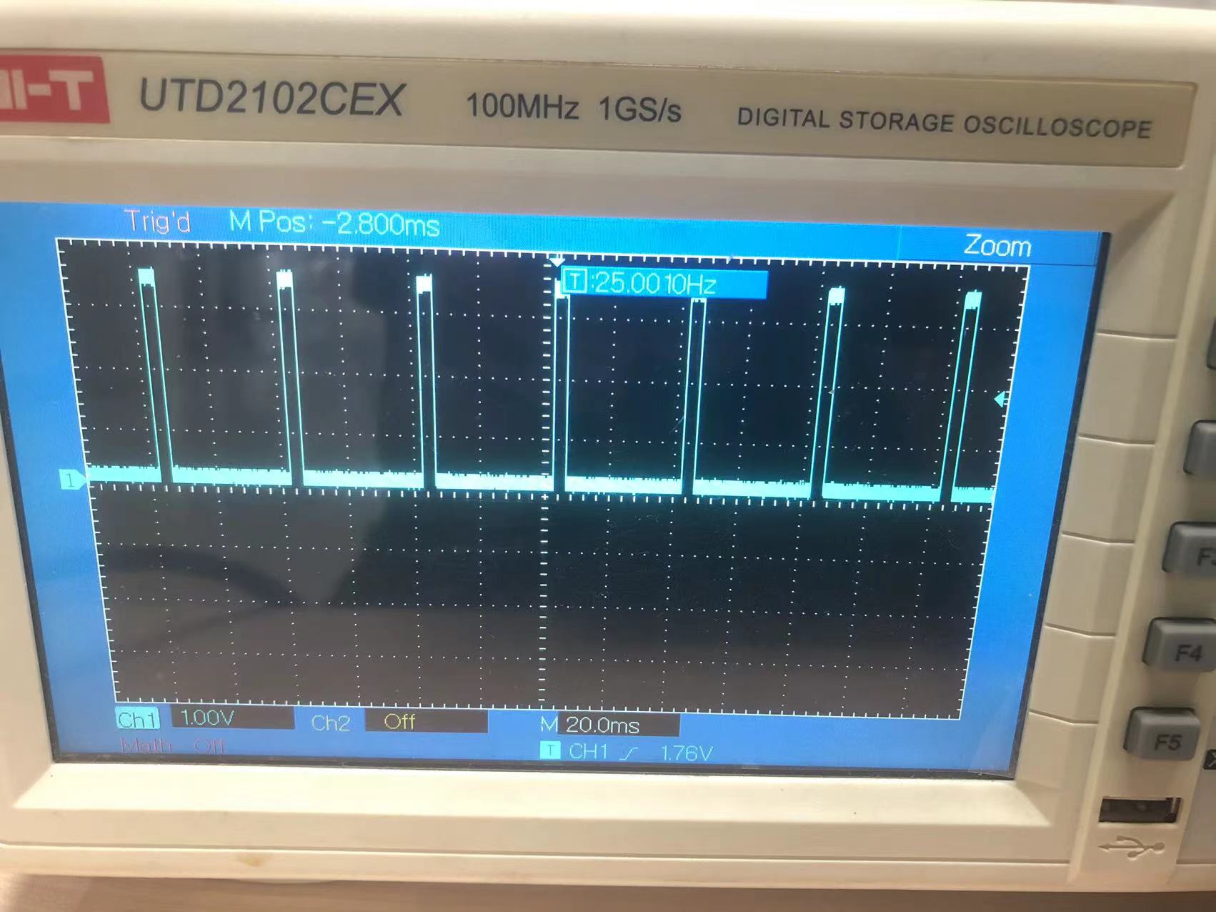
20hz The signal is as follows :
边栏推荐
- Ros Learning (23) Action Communication Mechanism
- When grep looks for a process, it ignores the grep process itself
- Redis configuration class redisconfig
- 454 Baidu Mianjing 1
- Drag to change order
- 猫猫回收站
- Centos8 install MySQL 8.0 using yum x
- ZOJ problem set – 2563 long dominoes [e.g. pressure DP]
- Appium自动化测试基础 — uiautomatorviewer定位工具
- The foreground downloads network pictures without background processing
猜你喜欢

组合导航:中海达iNAV2产品描述及接口描述

Baidu flying general BMN timing action positioning framework | data preparation and training guide (Part 1)
爬虫实战(六):爬笔趣阁小说

Modify the system time of Px4 flight control
AcWing 361. Sightseeing cow problem solution (SPFA seeking positive ring)
Cisp-pte practice explanation (II)

Reptile practice (VI): novel of climbing pen interesting Pavilion

Integrated navigation: product description and interface description of zhonghaida inav2
ROS learning (XX) robot slam function package -- installation and testing of rgbdslam
Box stretch and pull (left-right mode)
随机推荐
Redis tool class redisutil (tool class III)
【唯一】的“万字配图“ | 讲透【链式存储结构】是什么?
centos8安装mysql报错:The GPG keys listed for the “MySQL 8.0 Community Server“ repository are already ins
[unique] what is the [chain storage structure]?
Blue Bridge Cup 2022 13th provincial competition real topic - block painting
First experience of JSON learning - the third-party jar package realizes bean, list and map to create JSON format
Add PDF Title floating window
Let's see how to realize BP neural network in Matlab toolbox
猫猫回收站
Appium foundation - appium inspector positioning tool (I)
ROS learning (26) dynamic parameter configuration
LeetCode. Sword finger offer 62 The last remaining number in the circle
Appium基础 — Appium Inspector定位工具(一)
JS ES5也可以創建常量?
Ds-5/rvds4.0 variable initialization error
STM32F4---通用定时器更新中断
ROS learning (25) rviz plugin
Right mouse button customization
String to date object
Make DIY welding smoke extractor with lighting