当前位置:网站首页>Talk about SOC startup (VI) uboot startup process II
Talk about SOC startup (VI) uboot startup process II
2022-07-07 11:26:00 【lgjjeff】
This paper is based on the following software and hardware assumptions :
framework :AARCH64
Software :Uboot 2021.10-rc1
1 Uboot Main features supported
uboot After initialization, a command line interactive interface will be provided for users , The user can execute uboot Defined commands , To view the system status , Set environment variables and system parameters . In order to facilitate the management of hardware and drivers ,uboot Similar technologies have also been introduced linux Device tree and driver model features of the kernel . Of course , In order to increase the configurability of the system 、 Debuggability and traceability , It also supports environment variables 、log management 、bootstage Statistics and simple ftrace And so on . Now we will briefly introduce some of the more important features
1.1 Device tree
The device tree is a way of passing dts Document to describe SOC attribute , By separating the specific configuration information of the device from the driver , To achieve the mechanism of adapting multiple devices with one code .dts The file contains a series of hierarchical nodes and attributes , It can go through dtc The compiler compiles into binary suitable for device parsing dtb file .uboot The use of the device tree includes the following processes : Add dts file 、 Select a run-time dtb file 、 Enable device tree . The following is a detailed introduction :
(1) How to add a dts file
stay arch/<arch>/dts Under the table of contents , Add one xxx.dts file , This file can be copied from the kernel , Or in uboot dts Select another target board under the directory dts Based on , Then modify it according to the actual needs . After the modification is completed , stay arch/arm/dts/Makefile Add compilation options to it :
dtb-$(CONFIG_yyy) +=xxx.dtb
among yyy To use this dts Target board of
(2) How to select for the target board dts file
uboot The device tree file for is located in arch/<arch>/dts Under the table of contents , You can choose a default dts file :
CONFIG_DEFAULT_DEVICE_TREE="xxx”
This is because it is different from the kernel ,uboot The final image will match dtb Packaged in an image file , Therefore, in the compilation process, you need to know what is ultimately used dtb. About uboot The mirror with dtb The relationship between them will be described in detail later
(3) Specify dts
Sometimes when compiling, you want to use a that is not specified by default dts, You can add DEVICE_TREE=zzz Way to specify a new dts file , An example of this is :
make DEVICE_TREE=zzz
(4) How to enable the device tree
By configuring CONFIG_OF_CONTROL Option to enable device tree support
uboot And dtb There are several packaging combinations :
(1) If you define CONFIG_OF_EMBED Options , It will be dtb Specify one with __dtb_dt_begin A separate paragraph at the beginning ,dtb The content of will be directly linked to uboot.bin In the mirror . It is officially recommended that this method be used only in the development and debugging stages , Not for the production stage
(2) If you define CONFIG_OF_SEPARATE Options ,dtb Will be compiled as u-boot.dtb file , and uboot The original image is compiled as u-boot-nodtb.bin file , And connect them to the final uboot.bin file :
cat u-boot-nodtb.bin u-boot.dtb >uboot.bin
1.2 Drive model DM
Uboot Drive models and linux The device model of is similar , With it, the device can be separated from the drive . It can provide a unified operation interface for the same kind of equipment , The following can provide a standard registration interface for the driver , So as to improve the reusability and portability of the code . meanwhile , The driving model is organized by a tree structure uboot All devices in , It provides convenience for the unified management of equipment by the system .
1.2.1 Structure of driving model
The driver model is mainly used to manage the drivers and devices in the system ,uboot The following description structures are provided for them :
(1)driver Structure
driver Structure is used to represent a driver , Its definition is as follows :
struct driver {

	char *name;
	enum uclass_id id;
	const struct udevice_id *of_match;
	int (*bind)(struct udevice *dev);
	int (*probe)(struct udevice *dev);
	int (*remove)(struct udevice *dev);
	int (*unbind)(struct udevice *dev);
	int (*of_to_plat)(struct udevice *dev);
	int (*child_post_bind)(struct udevice *dev);
	int (*child_pre_probe)(struct udevice *dev);
	int (*child_post_remove)(struct udevice *dev);
	int priv_auto;
	int plat_auto;
	int per_child_auto;
	int per_child_plat_auto;
	const void *ops;	/* driver-specific operations */
	uint32_t flags;
#if CONFIG_IS_ENABLED(ACPIGEN)
	struct acpi_ops *acpi_ops;
#endif
}
Drivers can be registered in the system through the following interfaces :
#define U_BOOT_DRIVER(__name) \ ll_entry_declare(struct driver, __name, driver)
among ll_entry_declare Is defined as follows :
#define ll_entry_declare(_type, _name, _list) \ _type _u_boot_list_2_##_list##_2_##_name __aligned(4) \ __attribute__((unused)) \ __section(".u_boot_list_2_"#_list"_2_"#_name)
That is, it will define a struct driver Type of _u_boot_list_2_driver_2_#_name Variable , This variable needs to be placed in .u_boot_list_2_driver_2_#_name In the paragraph . Let's take a look at these section How is it stored in the link script , The following is a armv8 Schema link script arch/arm/cpu/armv8/u-boot.lds Defined in the .
 .u_boot_list : {

     KEEP(*(SORT(.u_boot_list*)));
 }
From the definition, we can see that these are .u_boot_list At the beginning section Will be saved together , And they will follow section Sort the names of before saving . This is mainly to facilitate traversal of these structures , For example, we need to traverse all registered driver, Can be obtained through the following code driver The starting address of the structure and the total driver Number .
struct driver *drv =
			ll_entry_start(struct driver, driver);                     (1-1)
int n_ents = ll_entry_count(struct driver, driver);                    (1-2)
(1-1) Get registered driver From
(1-2) Get registered driver The number of
among ll_entry_start and ll_entry_coun Is defined as follows :
#define ll_entry_start(_type, _list) \ ({
       \ static char start[0] __aligned(CONFIG_LINKER_LIST_ALIGN) \ __attribute__((unused)) \ __section(".u_boot_list_2_"#_list"_1"); \ (1-3)
	(_type *)&start;						\
})

#define ll_entry_end(_type, _list) \ ({
       \ static char end[0] __aligned(4) __attribute__((unused)) \ __section(".u_boot_list_2_"#_list"_3"); \ (1-4)
	(_type *)&end;							\
})

#define ll_entry_count(_type, _list) \ ({
       \ _type *start = ll_entry_start(_type, _list); \
		_type *end = ll_entry_end(_type, _list);		\
		unsigned int _ll_result = end - start;			\               (1-5)
		_ll_result;						\
	})
(1-3) Define a .u_boot_list_2_"#_list"_1 Section of , If you need to traverse driver, Then the name of this paragraph is .u_boot_list_2_driver_1, That is, it is located in all actual driver section Previous position
(1-4) Define a .u_boot_list_2_"#_list"_3 Section of , If you need to traverse driver, Then the name of this paragraph is .u_boot_list_2_driver_3, That is, it is located in all actual driver section The position after
(1-5) Through the above two labels, you can easily obtain the start and end addresses of drivers and calculate the total number of registered drivers
Finally, we give .u_boot_list_2 type section Layout in memory :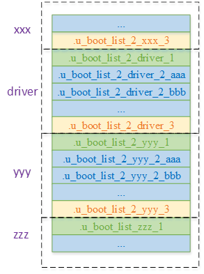
(2)uclass_driver Structure
uclass_driver Structure is used to represent a uclass drive , Its definition is as follows :
struct uclass_driver {

	const char *name;
	enum uclass_id id;
	int (*post_bind)(struct udevice *dev);
	int (*pre_unbind)(struct udevice *dev);
	int (*pre_probe)(struct udevice *dev);
	int (*post_probe)(struct udevice *dev);
	int (*pre_remove)(struct udevice *dev);
	int (*child_post_bind)(struct udevice *dev);
	int (*child_pre_probe)(struct udevice *dev);
	int (*child_post_probe)(struct udevice *dev);
	int (*init)(struct uclass *class);
	int (*destroy)(struct uclass *class);
	int priv_auto;
	int per_device_auto;
	int per_device_plat_auto;
	int per_child_auto;
	int per_child_plat_auto;
	uint32_t flags;
};
Its registration and traversal methods are the same as driver Exactly the same , Just the structure type and section Names are different , The following is its definition :
#define UCLASS_DRIVER(__name) \ ll_entry_declare(struct uclass_driver, __name, uclass_driver)
(3)udevice Structure
udevice In the driver model, it is used to represent a device bound to the driver , Its definition is as follows :
struct udevice {

	const struct driver *driver;
	const char *name;
	void *plat_;
	void *parent_plat_;
	void *uclass_plat_;
	ulong driver_data;
	struct udevice *parent;
	void *priv_;
	struct uclass *uclass;
	void *uclass_priv_;
	void *parent_priv_;
	struct list_head uclass_node;
	struct list_head child_head;
	struct list_head sibling_node;
#if !CONFIG_IS_ENABLED(OF_PLATDATA_RT)
	u32 flags_;
#endif
	int seq_;
#if !CONFIG_IS_ENABLED(OF_PLATDATA)
	ofnode node_;
#endif
#ifdef CONFIG_DEVRES
	struct list_head devres_head;
#endif
#if CONFIG_IS_ENABLED(DM_DMA)
	ulong dma_offset;
#endif
}
Everything in the system udevice The structure can be through parent、child_head and sibling_node come together , And finally hang to gd Of dm_root Node , So we can get through gd->dm_root Traverse all udevice equipment . The picture below is udevice The connection of , Each of these nodes has parent Point to its parent node ,sibling Point to its sibling node , and child Point to the child node .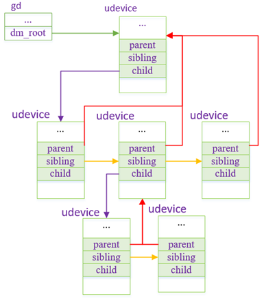
Because each udevice All belong to one uclass, So in addition to being connected to gd->dm_root Outside the list ,udevice It will be hung up uclass In the linked list . The connection between them will be introduced below uclass When given .
udevice It is dynamically created according to the scanned device in the initialization process of the driving model , stay uboot The actual device in can be defined in the following two ways :
(3-1)devicetree The way : This way through devicetree Maintain equipment information ,uboot When driving model initialization , Obtain device information by parsing the device tree , And complete its binding with drivers
(3-2) Hard coding : In this way, you can define a device through the following macro :
#define U_BOOT_DRVINFO(__name) \ ll_entry_declare(struct driver_info, __name, driver_info)
(4)uclass Structure
uclass Used to represent a class of equipment with the same function , Thus, a unified device access interface can be abstracted , It is convenient for other modules to call it . The following is a uclass The definition of :
struct uclass {

	void *priv_;
	struct uclass_driver *uc_drv;
	struct list_head dev_head;
	struct list_head sibling_node;
}
uclass Attach all devices belonging to this category to their dev_head On the list , At the same time, all in the system uclass It will be linked to a global linked list gd->uclass_root On . Its structure is as follows :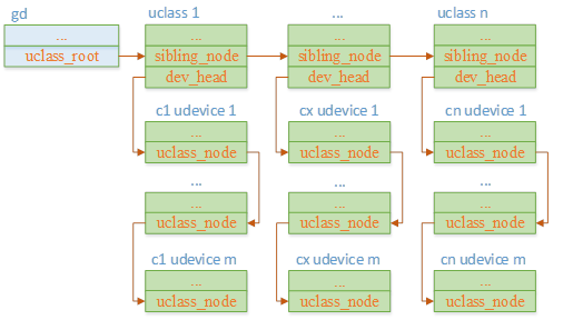
1.2.2 Drive the initialization of the model
The initialization of the driving model is mainly completed udevice、driver as well as ucalss And so on , It mainly includes the following parts :
(1)udevice And driver The binding of
(2)udevice And uclass The binding of
(3)uclass And uclass_driver The binding of
The process passes dm_init_and_scan Function implementation , It will be scanned separately by U_BOOT_DRVINFO as well as devicetree Defined devices , Assign them udevice Structure , And complete it with driver and uclass Operations such as binding relationship between . It should be noted that this function is in board_init_f and board_init_r Will be called , among board_init_f It is mainly to resolve the device nodes that need to be used before relocation , This type of node is in devicetree Will add u-boot,dm-pre-reloc attribute . This code flow is relatively clear , Students who are interested in it can analyze it by themselves
1.3 environment variable
The environment variable can be uboot Provide the ability to dynamically configure parameters at runtime , Such as modifying environment variables on the command line bootargs You can change the startup parameters of the kernel . It uses env=value Format store , Each environment variable is represented by '\0' ending . According to the configuration parameters of the system ,uboot stay include/env_default.h A default environment variable is defined for the system :
#ifdef DEFAULT_ENV_INSTANCE_EMBEDDED
env_t embedded_environment __UBOOT_ENV_SECTION__(environment) = {

#ifdef CONFIG_SYS_REDUNDAND_ENVIRONMENT
	1,
#endif
	{

#elif defined(DEFAULT_ENV_INSTANCE_STATIC)
static char default_environment[] = {

#elif defined(DEFAULT_ENV_IS_RW)
uchar default_environment[] = {

#else
const uchar default_environment[] = {

#endif
#ifndef CONFIG_USE_DEFAULT_ENV_FILE
#ifdef CONFIG_ENV_CALLBACK_LIST_DEFAULT
	ENV_CALLBACK_VAR "=" CONFIG_ENV_CALLBACK_LIST_DEFAULT "\0"
#endif
#ifdef CONFIG_ENV_FLAGS_LIST_DEFAULT
	ENV_FLAGS_VAR "=" CONFIG_ENV_FLAGS_LIST_DEFAULT "\0"
#endif
#ifdef CONFIG_USE_BOOTARGS
	"bootargs="	CONFIG_BOOTARGS			"\0"
#endif
#ifdef CONFIG_BOOTCOMMAND
	"bootcmd="	CONFIG_BOOTCOMMAND		"\0"
#endif

…

#ifdef CONFIG_EXTRA_ENV_SETTINGS
	CONFIG_EXTRA_ENV_SETTINGS
#endif
	"\0"
#else
#include "generated/defaultenv_autogenerated.h"
#endif
#ifdef DEFAULT_ENV_INSTANCE_EMBEDDED
	}
#endif
};
In this environment variable ,board By redefining CONFIG_EXTRA_ENV_SETTINGS The value of sets its own default environment variable , As for the qemu platform , Its definition lies in include/configs/qemu-arm.h:
#define CONFIG_EXTRA_ENV_SETTINGS \ "fdt_high=0xffffffff\0" \ "initrd_high=0xffffffff\0" \ "fdt_addr=0x40000000\0" \ "scriptaddr=0x40200000\0" \ "pxefile_addr_r=0x40300000\0" \ "kernel_addr_r=0x40400000\0" \ "ramdisk_addr_r=0x44000000\0" \ BOOTENV
Environment variables can be saved to fixed storage media after being modified ( Such as flash、mmc etc. ), In order to load the latest value after the next startup .Uboot adopt U_BOOT_ENV_LOCATION Macro defines the storage location of environment variables , For example, for mmc Its definition is as follows (env/mmc.c):
U_BOOT_ENV_LOCATION(mmc) = {

	.location	= ENVL_MMC,
	ENV_NAME("MMC")
	.load		= env_mmc_load,
#ifndef CONFIG_SPL_BUILD
	.save		= env_save_ptr(env_mmc_save),
	.erase		= ENV_ERASE_PTR(env_mmc_erase)
#endif
}
Environment variables in mmc The specific storage location in can be configured through options or devicetree Set up , As for the mmc:
(1)devicetree The method can be in /config Set the following properties in the node
u-boot,mmc-env-partition: Specify the partition where the environment variables are stored , Environment variables are stored at the end of the partition
u-boot,mmc-env-offset: If not defined u-boot,mmc-env-partition attribute , Then this parameter is used to specify the environment variable in mmc Offset on raw device
u-boot,mmc-env-offset-redundant: Specify the backup environment variable in mmc Offset on the device
(2) Set by configuring parameters
CONFIG_ENV_OFFSET: And u-boot,mmc-env-offset The meaning is the same
CONFIG_ENV_OFFSET_REDUND: And u-boot,mmc-env-offset-redundant The meaning is the same
The following options are used to configure the length of the environment variable and the device it saves :
(1)CONFIG_ENV_SIZE: Maximum length of environment variable
(2)CONFIG_ENV_IS_IN_XXX( Such as CONFIG_ENV_IS_IN_MMC): The device type saved by the environment variable
(3)CONFIG_SYS_MMC_ENV_DEV: Equipment number saved by environment variable
uboot For environment variables saved in fixed media crc32 Verify data integrity , If the data is destroyed, the default environment variable will be used to reinitialize the value of the environment variable
1.4 Command line
uboot After initialization, you can press the key to enter the command line window , In this window, you can set environment variables , Download the image file , Start the kernel and other commands , The support of these commands is greatly convenient uboot Debugging of processes related to kernel startup .uboot There are many built-in commands , Such as md、mw、setenv、saveenv、tftpboot、bootm etc. ,uboot The following macros are provided for command definition (include/command.h):
(1)U_BOOT_CMD
It is used to define a uboot command , Its definition is as follows :
#define U_BOOT_CMD(_name, _maxargs, _rep, _cmd, _usage, _help) \ U_BOOT_CMD_COMPLETE(_name, _maxargs, _rep, _cmd, _usage, _help, NULL)
The meaning of parameters is as follows :
_name: Command name
_maxargs: Maximum number of parameters
_rep: Whether the command is repeatable .cmd_rep The callback will output whether it is repeatable ( After pressing enter , If the last executed command is executed again, it is repeatable )
_cmd: Command processing functions
_usage: The use of information , perform help Short message displayed when
_help: Help information ( perform help name Detailed usage information displayed when )
(2)U_BOOT_CMD_WITH_SUBCMDS
It is used to define a command with uboot command , Subcommands can avoid too much logic in the main command processing function , You can also define your own for each subcommand _rep Parameters , To independently handle whether it can be repeatedly executed .
The following is its definition :
#define U_BOOT_CMD_WITH_SUBCMDS(_name, _usage, _help, ...) \ U_BOOT_SUBCMDS(_name, __VA_ARGS__) \ U_BOOT_CMDREP_COMPLETE(_name, CONFIG_SYS_MAXARGS, do_##_name, \ _usage, _help, complete_##_name)
Its fixed parameters are as follows :
_name: Main command name
_usage: The use of information , perform help Short message displayed when
_help: Help information ( perform help name Detailed usage information displayed when )
The variable parameter section can be used to define subcommands U_BOOT_SUBCMD_MKENT, Its definition is as follows :
#define U_BOOT_SUBCMD_MKENT(_name, _maxargs, _rep, _do_cmd) \ U_BOOT_SUBCMD_MKENT_COMPLETE(_name, _maxargs, _rep, _do_cmd, \ NULL)
The parameters of the subcommand are as follows :
_name: Subcommand name
_axargs: The maximum number of parameters of the subcommand
_rep: Whether the subcommand can be executed repeatedly
_do_cmd: The command processing function of the subcommand
(3) With wdt Command as an example (cmd/wdt.c), It defines the main command wdt, And define the subcommand list、dev、start etc.
static char wdt_help_text[] =
	"list - list watchdog devices\n"
	"wdt dev [<name>] - get/set current watchdog device\n"
	"wdt start <timeout ms> [flags] - start watchdog timer\n"
	"wdt stop - stop watchdog timer\n"
	"wdt reset - reset watchdog timer\n"
	"wdt expire [flags] - expire watchdog timer immediately\n";

U_BOOT_CMD_WITH_SUBCMDS(wdt, "Watchdog sub-system", wdt_help_text,
	U_BOOT_SUBCMD_MKENT(list, 1, 1, do_wdt_list),
	U_BOOT_SUBCMD_MKENT(dev, 2, 1, do_wdt_dev),
	U_BOOT_SUBCMD_MKENT(start, 3, 1, do_wdt_start),
	U_BOOT_SUBCMD_MKENT(stop, 1, 1, do_wdt_stop),
	U_BOOT_SUBCMD_MKENT(reset, 1, 1, do_wdt_reset),
	U_BOOT_SUBCMD_MKENT(expire, 2, 1, do_wdt_expire));
(4) If we need to customize a command , Refer to the following process ( With test_cmd Command as an example )
a stay cmd Create a source file under the directory test_cmd.c
b In this directory Makefile Add Compilation Rules to :
obj-$(CONFIG_CMD_TEST_CMD) += test_cmd.o
c In this directory Kconfig Add corresponding configuration items to the file CONFIG_CMD_TEST_CMD
d stay test_cmd.c Macro adding commands are defined according to the signed commands , And implement its command processing function
2 Board_init_f and board_init_r Function flow
board_init_f and board_init_r The function logic of is relatively clear , Next, we only give the call flow chart , Instead of going into the details
2.1 board_init_f technological process
board_init_f yes uboot Process before relocation , It includes some basic module initialization and relocation related preparations . The following is the function in armv8 Possible execution processes under the architecture , The dotted box in the figure indicates that the process is configurable , Solid wireframe is mandatory .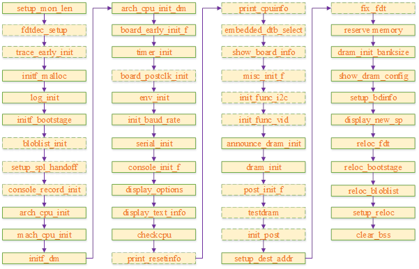
2.2 board_init_r technological process
board_init_r yes uboot The process to be performed after relocation , It contains basic modules 、 Initialization of hardware drivers and board level features , And finally through run_main_loop start-up os Or enter the command line window .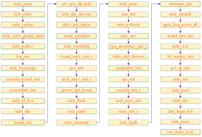
边栏推荐
- Android 面试知识点
- The post-90s resigned and started a business, saying they would kill cloud database
- 如何在博客中添加Aplayer音乐播放器
- Activity生命周期
- [untitled]
- 软件设计之——“高内聚低耦合”
- 创意信息获2家机构调研:GreatDB 数据库已在9地部署
- electron添加SQLite数据库
- 【问道】编译原理
- STM32 entry development NEC infrared protocol decoding (ultra low cost wireless transmission scheme)
猜你喜欢
Socket socket programming
Unsupervised learning of visual features by contracting cluster assignments
OneDNS助力高校行业网络安全
![[pyqt] the cellwidget in tablewidget uses signal and slot mechanism](/img/0e/02265f7195ca0add4155694530822a.png)
[pyqt] the cellwidget in tablewidget uses signal and slot mechanism
一度辍学的数学差生,获得今年菲尔兹奖
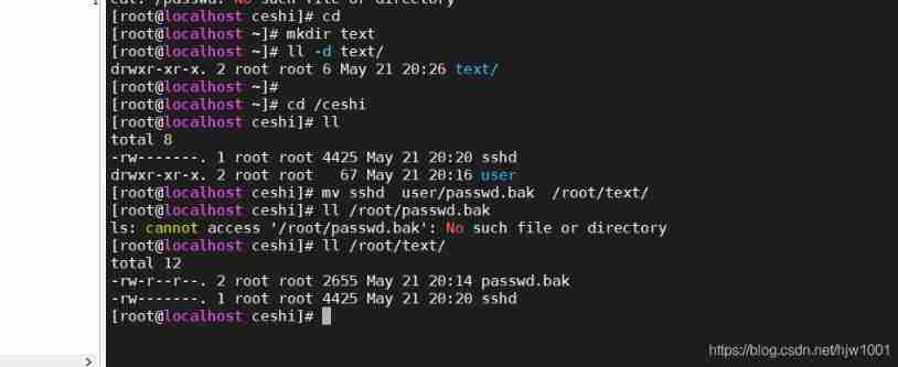
2021-05-21
![Verilog realizes nixie tube display driver [with source code]](/img/ad/be94912bedc738f4b5f97138db7352.png)
Verilog realizes nixie tube display driver [with source code]

The annual salary of general test is 15W, and the annual salary of test and development is 30w+. What is the difference between the two?

Zhou Yajin, a top safety scholar of Zhejiang University, is a curiosity driven activist
浙江大学周亚金:“又破又立”的顶尖安全学者,好奇心驱动的行动派
随机推荐
CentOS系统下Redis安装和自启动配置的步骤
Qt|多个窗口共有一个提示框类
Go redis Middleware
创意信息获2家机构调研:GreatDB 数据库已在9地部署
[encapsulation of time format tool functions]
Leetcode - interview question 17.24 maximum submatrix
Two week selection of tdengine community issues | phase II
[untitled]
About the application of writing shell script JSON in JMeter
STM32 entry development uses IIC hardware timing to read and write AT24C08 (EEPROM)
Zhou Yajin, a top safety scholar of Zhejiang University, is a curiosity driven activist
QT implements the delete method of the container
Android 面试知识点
Vuthink proper installation process
深度学习秋招面试题集锦(一)
关于jmeter中编写shell脚本json的应用
常用sql语句整理:mysql
[untitled]
软件设计之——“高内聚低耦合”
The annual salary of general test is 15W, and the annual salary of test and development is 30w+. What is the difference between the two?