当前位置:网站首页>What is the method of manual wiring in PCB design in 22protel DXP_ Chengdu electromechanical Development Undertaking
What is the method of manual wiring in PCB design in 22protel DXP_ Chengdu electromechanical Development Undertaking
2022-07-07 08:32:00 【u010755676】
SO SCM development guide 22
The road to the ends of the earth is long , One step at a time, one can expect . This article is introduced in Protel DXP in PCB The method of manual wiring in the drawing .
One 、 Drawing layers
Manual wiring needs to be done in the wiring layer , Generally, the wiring layer in the double-sided board is :
->Top Layer( Top layer wiring layer );
->Bottom Layer( Bottom wiring layer );
Layer switching is carried out in the layer management bar at the bottom .
Two 、 Tools to be used for manual wiring
Generally, manual wiring requires two tools , You can find :
-> Line drawing tools . In the wiring layer , Used to draw the wires on the circuit board .
-> Through hole tool . A via is a conductive hole , Used to connect wires in different wiring layers .

3、 ... and 、 Overview of manual cabling process
-> Set routing rules . For manual wiring , Line width does not need to be set , Because the line width is input by the operator .
The line spacing needs to be set , Although the line spacing is also drawn by the operator , But the line spacing rule is set , It is convenient to check , Because once the line spacing is smaller than the rule setting when drawing , The system will alarm , Mark the narrow lines with other colors .
The turning angle of the line needs to be set , Generally set as 45 degree , It is convenient to draw manually .
-> In the wiring layer , Use the line drawing tool to draw the lines that need to be connected .
-> When you need to connect across layers , Connect with a through-hole tool .
Four 、 Illustration of manual wiring
Then we will follow the previous simple example , Use a diagram to illustrate .
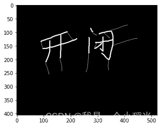
- The original state before wiring
chart 2 It's original and has not been wired PCB chart , You can see , The pins to be connected are temporarily connected by flying wires , The goal of cabling is : Formal and standardized wiring , Remove flying wire .

- Set rules
As I said before , Wiring rules need to be set in the rules and Constraints Editor , Open at :Design/rules,
Enter the rules and Constraints Editor , Manual wiring requires at least two rules : Line spacing and corner ,

- wiring
Wiring needs to be done in the wiring layer .
The wiring process is to click the line drawing tool in the toolbar above , Click the starting point of wiring ( Generally, it is pad ), Start Wiring , Determine the direction and route , Click the end point ( Generally, it is also a pad ).
Change the line width : After starting wiring , Click on the Tab key , A dialog box for changing the line width pops up , You can set the line width here , Pictured 4.


4、 Place vias
Vias are generally used for cross layer wiring , Used to connect components between different wiring layers , Here are mainly pads .
Typical application scenarios :
-> When conventional wiring is difficult , We need to use vias to relay ;
-> Used for bonding pad cross layer connection of surface mounted components, etc .
Key points of operation :
There are no wires in all wiring layers 、 Place vias at the pad , Connect the via wire to the first pad 、 Connect through other holes , Then switch to another wiring layer , Then connect to other target pads or vias from this via .

5、 Remove flying wire
When all wiring is completed , You can remove the flying wire , It looks better like this . Of course, it seems that you can ignore it , Circuit board manufacturers can also process .
Method of removing flying wire :
Double click the pad where the flying wire is to be removed , eject pad Dialog box , stay net The column is adjusted to no net, Set to no label , Naturally, the flying line is removed .

6、 complete

5、 ... and 、 Summary
Although manual wiring takes a little time , But the parameters and direction of the line can be determined according to the intention of the operator , It is very important in high-quality circuit board design .
At the end of this section , Wonderful to be continued . Provide single chip microcomputer 、PLC、 Circuit board 、 controller 、 Instruments and Apparatuses 、 Software 、APP、 Electromechanical equipment or system 、 Industrial control 、 Automatic control system 、 Control system development and design customization , Contact figure 6 website .
边栏推荐
- In go language, function is a type
- IELTS review progress and method use [daily revision]
- Four items that should be included in the management system of integral mall
- Splunk子查询模糊匹配csv中字段值为*
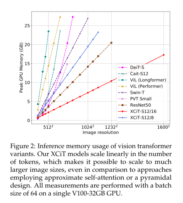
- XCiT学习笔记
- The truth of robot education in hands-on practice
- Xcit learning notes
- Use of any superclass and generic extension function in kotlin
- 2-3 lookup tree
- Input and output of floating point data (C language)
猜你喜欢
Opencv learning note 4 - expansion / corrosion / open operation / close operation
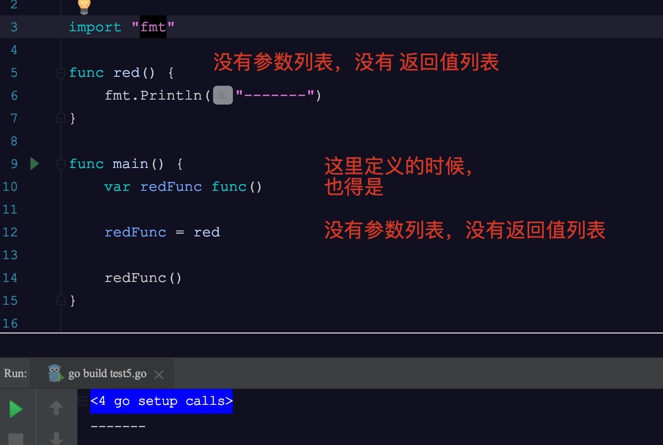
Go语言中,函数是一种类型
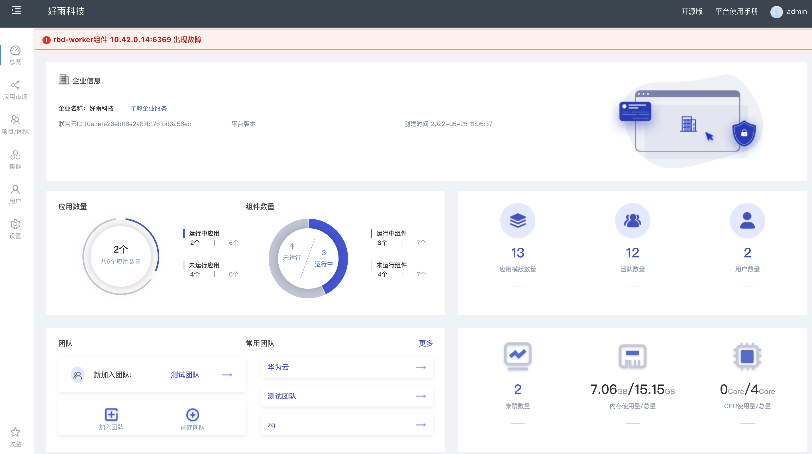
Rainbow 5.7.1 supports docking with multiple public clouds and clusters for abnormal alarms
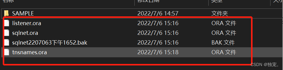
PLSQL的安装和配置
Easy to understand SSO
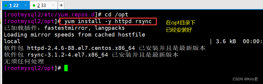
Rsync remote synchronization
单元测试报告成功率低
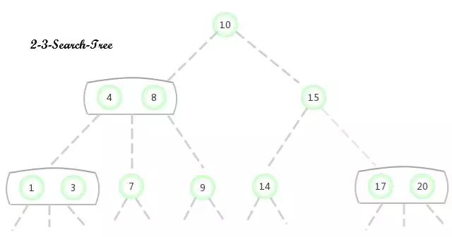
2-3 lookup tree
The truth of robot education in hands-on practice
XCiT学习笔记
随机推荐
Golang compilation constraint / conditional compilation (/ / +build < tags>)
Through the "last mile" of legal services for the masses, fangzheng Puhua labor and personnel law self-service consulting service platform has been frequently "praised"
Implementation method of data platform landing
机器人教育在动手实践中的真理
Splunk query CSV lookup table data dynamic query
解析创新教育体系中的创客教育
Practice of combining rook CEPH and rainbow, a cloud native storage solution
Analysis of maker education in innovative education system
The truth of robot education in hands-on practice
Opencv learning notes 1 -- several methods of reading images
[quick start of Digital IC Verification] 14. Basic syntax of SystemVerilog learning 1 (array, queue, structure, enumeration, string... Including practical exercises)
National standard gb28181 protocol video platform easygbs adds streaming timeout configuration
POJ - 3616 Milking Time(DP+LIS)
Infix keyword infix expression and the use of generic extension function in kotlin
2 - 3 arbre de recherche
Exercise arrangement 2.10, 11
A method for quickly viewing pod logs under frequent tests (grep awk xargs kuberctl)
IP-guard助力能源企业完善终端防泄密措施,保护机密资料安全
JEditableTable的使用技巧
SSM integration