当前位置:网站首页>High quality USB sound card / audio chip sss1700 | sss1700 design 96 kHz 24 bit sampling rate USB headset microphone scheme | sss1700 Chinese design scheme explanation
High quality USB sound card / audio chip sss1700 | sss1700 design 96 kHz 24 bit sampling rate USB headset microphone scheme | sss1700 Chinese design scheme explanation
2022-07-08 01:09:00 【qq1659747718】
The high quality USB Sound card / Audio chip SSS1700|SSS1700 Design 96 KHz 24 Bit sampling rate USB Headset microphone scheme |SSS1700 Explanation of Chinese design scheme
Taiwan Xinchuang is 2021 A new product launched in SSS1700, It is a high-quality product USB Sound card / Audio chip , have 96 KHz 24 Bit sampling rate and external audio codec (24 position /96 KHz I2S Input and output ), And has built-in stereo 16/24 position ADC、 stereo 16/24 position DAC、 Headset driver 、 Five band hardware EQ、, Audio PLL ,USB Clock oscillator , and USB FS Controller plus physical layer . external 24C02~24C16 EEPROM Connect as USB VID/PID/ Product string 、 Default gain settings and other customization requirements provide flexibility .
SSS1700 Parameter characteristics of :
accord with USB standard v2.0 Run at full speed
accord with USB Audio equipment class specification v1.0
Support 44.1KHz/48KHz/96KHz、16 position /24 Bit sampling rate (EEPROM Option )
Embedded digital mixer , After power on, the default mixer is silent ( Operating system control )
When setting sheet ADC when , Two DAC All channels are related to the order ADC Data mixing
When setting stereo ADC when ,L-ch DAC And L-ch ADC Data mixing ,R-ch DAC And R-ch ADC Data mixing
Power mode setting ROM Options (USB Bus power supply 100mA: Default or 500mA To configure )
The default support 16 and 24 position ,48KHz Sampling rate ADC and DAC
Embedded earphone driver , the height is 16 Ohmic load drive
ADC Line input to DAC Output data path options
be used for 16/24 Bit codec DAC/ADC(EEPROM Option ) Embedded in I2S Interface ( Lord / Slave mode )
be used for 16/24 Bit codec DAC/ADC(EEPROM Option ) Embedded in SPDIF I / O interface
Embedded crystal free on-chip oscillator
Support USB Hang up / Recovery mode
be used for USB Embedded interface USB Transceiver
For Headphone Function ,USB The audio function topology has 2 Two input terminals ,2 Two output terminals ,(1 A mixer unit ),(1 A selector unit ) and (3) Functional units ( Some units can be through ROM Code options enable )
Support a control endpoint 、 A synchronous output endpoint 、 A synchronous input endpoint 、 An interrupt input endpoint (HID Use interrupt input and control output )
Standby zero bandwidth setting , Used to release when the device is inactive USB Playback bandwidth on the bus
The volume goes up 、 volume down 、 Play mute 、 Recording mute 、 Next track 、 Previous track 、 Stop and play / Pause pin , For users to directly control
The volume goes up 、 volume down 、 Play mute 、 Next track 、 Previous track 、 Stop and play / Suspend support
Two wire serial bus (I2C Bus ) For external use MCU Control the whole EEPROM Space can pass through MCU visit
For host control synchronization USB HID
External serial port EEPROM(24C02~24C16) Interface , For customer specific USB video 、PID、 Product string 、 Serial number 、 Default gain 、 Default EQ Set up 、 Play / Logging enabled and other options
EEPROM The write function passes HID Or the specific requirements of the supplier , Provide convenience for mass production
Preloaded VID、PID And product strings and design options to set priorities :i) external EEPROM ii) The embedded ROM
Customer specific requests and new virtual registers (10XX\u 10XX; among XX It can be set by register write back and read back , To verify ) For software protection
GPIO and MCU The interface register passes through HID read / Write
True headphone amplifier solution
Support CTIA/OMTP Automatic switch TRRS Audio jack (EEPROM Option )
Support AD Key detection (EEPROM Options )
Support RGB LED(EEPROM Option )
Support HID keyboard (EEPROM Option )
Support IIC Initial external codec (EEPROM Options )
The embedded 1.2V POR
The embedded 5V to 3.3V(250mA Capacity ) and 3.3V to 1.2V Regulator , For a single external 5V Power Supply
Embedded rotary encoder interface for volume control (EEPROM Option )
1.2V Digital core and audio PLL operation 、3.3V USB PLL Operation and ADC/DAC operation
compatible Win XP、Win 7、Win 10、Mac OS、Linux OS and Android OS, No additional driver required
SSS1700 Design characteristics and electrical parameters :
1. Absolute maximum rating
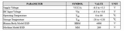
2. DC characteristics

3. Communication characteristics
Headphone output
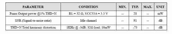
Microphone input characteristics

4. Pin description

48 foot LQFP/QFN Pin output diagram of
36 foot QFN Pin output diagram

Pin list
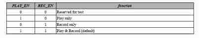
Play 、 Recording and function options
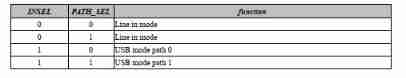
Insert path selection function options
5. Block diagram and description
USB The default setting of the line in mode

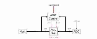
Automatic gain control (AGC)
SSS1700 have AGC( Automatic gain control ) function . It can automatically adjust ADC Output range , send ADC The output of is kept in a stable range .AGC The control schematic diagram is as follows , The gain adjustable range is -23dB~+40dB, Each level 1dB Adjustable .
AGC Parameter settings can be set in EEPROM Set in . Control characteristics include time stability 、 Error range 、 Active way 、 Retention time 、 Speed regulation, etc , These parameters need to be set separately . Its operation diagram is as follows: :
AGC The goal of tuning is to be within two blue lines . As shown in the previous figure , The signal is below the blue line interval , be AGC The amplifier adjusts the signal to the blue line range . Similarly , In the picture , The signal exceeds the blue interval , then AGC Reduce the signal to the blue range .

Multifunction buttons (4 key )
SSS1700 Most support 4 Multiple function keys . adopt EEPROM Set up , Each multifunction key can have up to four different button operation modes . The four different button operations are “ Short press ”、“ Short press... Twice in a row ”、“ Short press and long press ” and “ Long press ”.
Each multifunction key corresponds to a different control mode , To meet different functional requirements , So as to achieve the purpose of simplifying the number of keys . The setting diagram is as follows :

Key input can be set from the following positions : The function output can be assigned to :
LED Lamp effect function
SSS1700 It has the function of stereo audio waveform gradient indicator . adopt EEPROM Set up , Up to six indication signals can be provided (L/R The difference between the , Share three indication signals for each channel ). The indication signal can be connected to LED As an audio output gradient indicator . When the audio signal is zero ,LED It can be set as breathing lamp , To increase product diversity .
The following is the function diagram :

When setting the audio output indicator , It can be adjusted according to the required output range ; Each indicator signal can have 16 Make the recommended audio settings at two levels .
Five band equalizer
SSS1700 On the playback path 5 Equalization function of multiple frequency bands , Provide users with sound effect adjustment . These frequencies of the five band equalizer are fixed at 60Hz、300Hz、1.2KHz、3.6KHz and 12KHz. The gain of each frequency band can be set to +12dB~-∞dB, As shown below :

Users can adjust a variety of sound effects according to their needs , The adjusted sound effect is stored in EEPROM in , You can use a single button to change different sound effects in a circular way , It also provides a single LED Indicating switch sound effect . By default ,SSS1700 Built in a subwoofer sound settings , therefore , There's no outside EEPROM Under the circumstances , There is still one EQ Voice conversion for users . Preset bass ( Subwoofer ) The sound settings are as follows :

SSS1700 Detailed design 96 KHz 24 Bit sampling rate USB The block diagram of earphone microphone scheme is shown below :

边栏推荐
- Authorization code of Axure rp9
- 新库上线 | CnOpenData中华老字号企业名录
- Marubeni official website applet configuration tutorial is coming (with detailed steps)
- ReentrantLock 公平锁源码 第0篇
- FOFA-攻防挑战记录
- STL--String类的常用功能复写
- Vscode is added to the right-click function menu
- Letcode43: string multiplication
- 大二级分类产品页权重低,不收录怎么办?
- Chapter VIII integrated learning
猜你喜欢
Chapter VIII integrated learning
Chapter 16 intensive learning
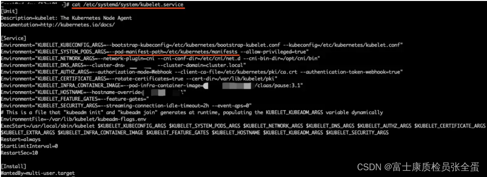
Kubernetes static pod (static POD)
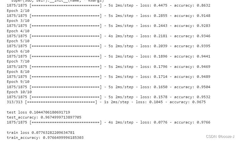
6.Dropout应用

基于人脸识别实现课堂抬头率检测
11. Recurrent neural network RNN
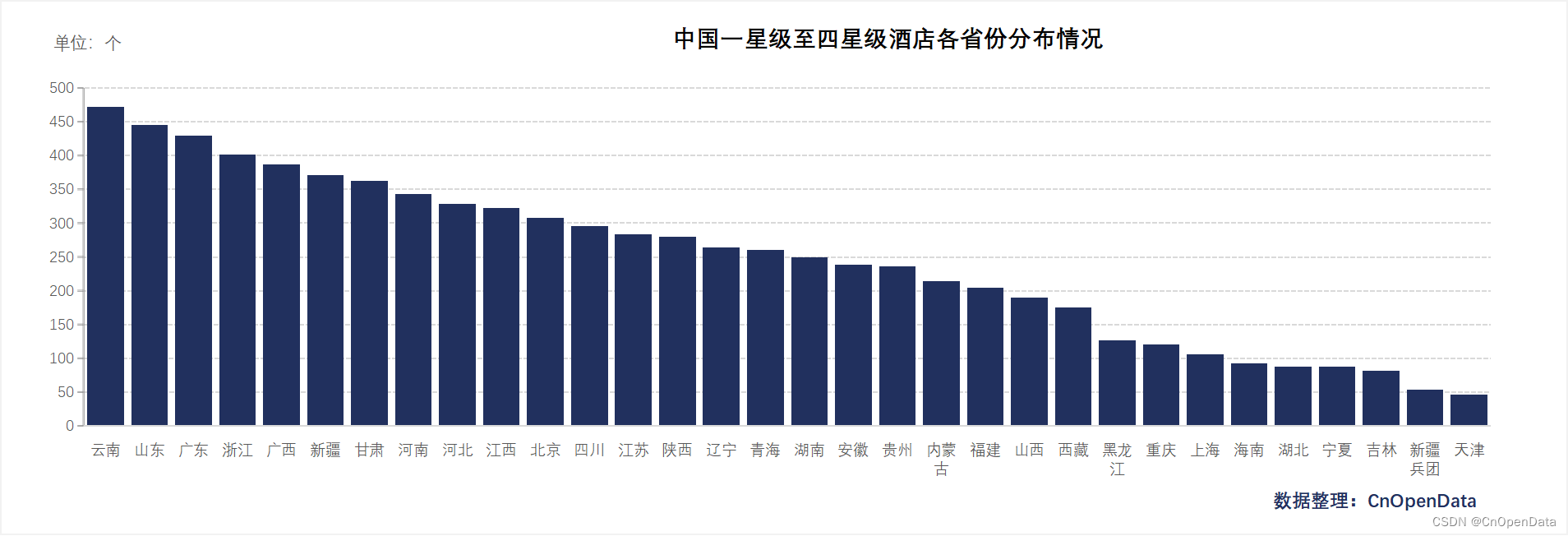
New library online | cnopendata China Star Hotel data
![[deep learning] AI one click to change the sky](/img/74/f2e854b9f24129bcd9376733c2369f.png)
[deep learning] AI one click to change the sky
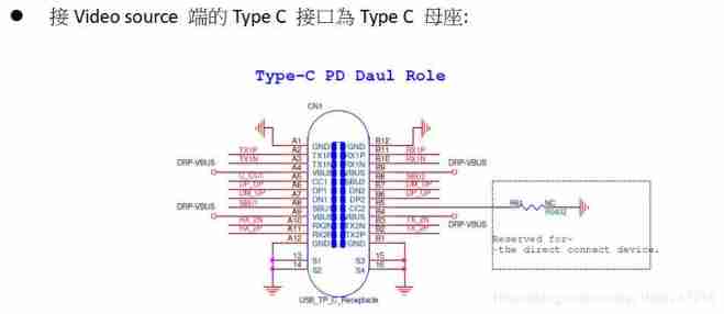
Ag9310 for type-C docking station scheme circuit design method | ag9310 for type-C audio and video converter scheme circuit design reference
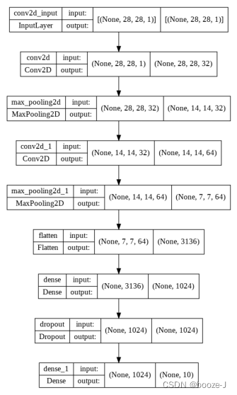
14.绘制网络模型结构
随机推荐
[go record] start go language from scratch -- make an oscilloscope with go language (I) go language foundation
炒股开户怎么最方便,手机上开户安全吗
网络模型的保存与读取
7. Regularization application
SDNU_ACM_ICPC_2022_Summer_Practice(1~2)
Fofa attack and defense challenge record
Two methods for full screen adaptation of background pictures, background size: cover; Or (background size: 100% 100%;)
My best game based on wechat applet development
New library launched | cnopendata China Time-honored enterprise directory
【深度学习】AI一键换天
Reentrantlock fair lock source code Chapter 0
3. MNIST dataset classification
6. Dropout application
How to write mark down on vscode
How does starfish OS enable the value of SFO in the fourth phase of SFO destruction?
11. Recurrent neural network RNN
The weight of the product page of the second level classification is low. What if it is not included?
[Yugong series] go teaching course 006 in July 2022 - automatic derivation of types and input and output
Analysis of 8 classic C language pointer written test questions
[note] common combined filter circuit